
Beware the Bear
Siberia Racing Tech Pages
Beware the Bear
![]()
Testing Lap Counters
The physical installation and configuration of a lap counter are just the first steps. Unless the entire lap counter system is rigorously tested after installation the job isn't done. Without testing there is no assurance that it will work in all instances. This article will go over methods I have used to test and verify operability of lap counters that use optical detectors and dead strips. I will briefly touch on other detection systems such as web cameras, micro switches, hall-effect sensors and reed switches.
Because the system was not rigerously tested the LED lap counter failed during the HOPRA nationals super stock main when cars started going over the dead strip faster than the counter could reliably detect them. This problem was undetected during preliminary races, practice, qualifying or the semis. It only happened in the main. Fortunately it was caught early in the race and the marshals kept the race director informed when cars missed a lap. In the main I was a marshal as was the individual who designed and built the tracks one of a kind digital lap counter. During the race he and I had a good discussion on what caused the problem, how to fix it and how to test the system following its repair. All this happened while smoke was pouring out of the nearby track owners ears. The track owner was informed that the lap counter might be unreliable during practice. He chose to ignore this information.
In a second case a TCP style lap counter was shown to be unreliable during qualifying due to a similar issue. The racers had to decide to either pack up and go home or to work together and count every lap by hand. The latter was done and the race went on.
The above two instances are not the only cases of lap counter failure I have personally experienced. They are just two of many. In my 50+ years of experience racing slot cars from 1/24th to HO I have seen almost every type of lap counter system fail. I have also seen almost every kind of lap counter system operate successfully. These system include systems triggered by reed switches, hall effect devices, dead strips and optical sensors. Over my career I have personally built three electro-mechanical four lane lap counter systems. I also developed a four and six lane lap counter/timer systems for the Atari personal computer. All of these systems were made to work reliably and to my knowledge did not experience a failure during there lifetimes. I repaired a few lap counter systems and I also did beta testing for both the Trakmate and Slottrak Race Management Systems (RMS). Beta testing included developing tests to verify that the RMS and its interface card(s) would detect unusually fast cars and simultaneous inputs from these unusually fast cars. My latest track, Magic Raceway, uses the Slottrak RMS with a first of a kind digital interface. This first of a kind interface uses commercially available infrared digital sensors and a Phidget 0/16/16 Digital Input/Output card.
The above track failures were caused by a channel update issue. Every lap counter system (mechanical or electrical) has a minimum time that the car must be over the sensor before the counter will detect and count it. Depending on the devices physical and electrical characteristics, this time can range from microseconds to milliseconds.
A millisecond is 1/1,000 of a second. A response time of several milliseconds sound fast. It really isn’t when you are dealing with three inch long cars traveling at an average speed of 20 feet (240 inches) per second. Assuming that an optical detector is being used, the time that a three inch long car traveling at 20 fps spends over the sensor is 3/240 = 0.0125 seconds or 12.5 milliseconds. When you consider that the fastest average recorded speed for a HO scale race distance (including gutter lanes and corners) is over 40 feet (480 inches) per second, a millisecond is not long at all.
Windows or other clear spaces in the body can adversely impact an optical systems detection time. At one major race front and rear windows had to be painted over to get cars to reliably count when they passed over the optical sensor. Dead strip tracks have had similar issues due to differences in pickups, pickup tension and/or pickup bounce.
The only reliable way I know of to test a lap counter system is to pass a car over the lap counter at a speed that is several times faster than the fastest cars you plan on racing. Remember that straight line speed is greater than average lap speed. Depending on the lap counters location, a car having an average speed of 12-16 Feet Per Second (FPS) over a lap could be significantly faster (20 FPS or more) when it crosses the lap counter.
My standard test for a lap counter using optical sensors is to add a wing to the front of a fast car. The wing extends into the adjacent lanes and trigger these lanes sensors while the car triggers its sensor. I have built test cars that have simultaneously tested sensors on four lane tracks. While I have not done it, I assume that a suitable test car could be made to simultaneously test all the lanes on a six or eight lane track. I have made wings out of paper, thin cardboard, model aircraft plywood and plastic. I then test the system by running the car for a minimum of 20 qualifying laps in a row. Twenty qualifying laps are possible but can be difficult to string together which is why I chose the value. If all lanes tested record the same number of laps then, and only then, do I consider the system to be reliable.
There are two types of time issues that we are trying to guard against. The first is the single channel update time. In other words how much time is required for a single channel to detect a car crossing the sensor. This is the only issue of concern if the track uses individual counter modules for each lane such as the track mentioned above. Unfortunately, the days of the TCP or the TrixTrax counters have past. The modern computer driven Race Management Systems (RMS) use an interface card that receives inputs from multiple sensors. This is true of systems that use an interface card and systems in which the sensors are connected directly to a serial or parallel port.
What we are concerned with for an RMS system is not only the time for a single channel to detect the car but also how often is the RMS looking at that channel and how often does the interface card report that channels status. If the RMS spends a millisecond looking at each channel it would take a minimum of 4 x 1 = 4 milliseconds to scan the sensors on a four lane track. However, if the interface card spends an additional 2 milliseconds to report the status of each sensor in sequence this could add an additional 4 x 2 = 8 milliseconds to the time necessary to scan all four sensors. The total update time could be 12 milliseconds or more. If the car is traveling over the counter at 20 FPS it only spends 12.5 milliseconds going over the detector. With such a system there is almost no margin for error.
Unfortunately the number of channels being scanned is not equal to the number of lanes on the track. The number of channels being scanned is equal to the number of channels on the interface card. If the interface card has eight input channels, the time to scan all of the inputs and report the data to the RMS could be 3 x 8 = 24 milliseconds and the counter would not be reliable. If the card has input and output channels it may be scanning the I/O channels sequentially. A card with eight input and eight output channels could have an update time of 3 x (8 + 8) = 48 milliseconds.
The scan rate was the problem on my latest lap counter design that used commercially available optical flame detection sensors and a Phidget 0/16/16 card/ The card has 16 digital inputs and 16 digital output. The Phiget board was connected to a Windows 10 PC with an I-7 processor that was running the Slottrak Race Management System. Available data indicated that each Phidget channel had a minimum detection time of 0.004 seconds. This is one third of 12.5 milliseconds and detection shouldn’t be a problem. In addition available data indicated that each channel could accept 125 inputs/second or one input every 0.008 seconds.
In the system's first test the card and software reacted well to one or two cars passing over the sensors simultaneously. When all three lanes were simultaneously triggered at speed one lane consistently failed to count. If the car crossed the sensors slowly then all three lanes counted. After some additional testing and parts swapping I determined that I had an update time issue. When a search of available data could not identify how the card scanned multiple channels I took the brute force approach to solving the problem.. Available data indicated that each channel could accept an input every 0.008 seconds. I conservatively assumed that the card scanned the 16 input channels and 16 output channels in sequential order. Based on this I was able to calculate that I needed to hold the inputs high for a minimum of 0.008 x (16 + 16) = 0.256 seconds to guarantee a reliable system.
I ended up adding a 0.4 second time delay circuit. Each lane has its own time delay circuit located between the sensor and the interface card. Each time delay circuit has an activation time of a few microseconds (a microsecond is 1/1,000,000 of a second). When activated, by a car passing over the optical sensor, the time delay circuit holds the interface channel input high for approximately 0.4 seconds. If the car remained on the sensor longer than 0.4 seconds there was no additional time delay when the car uncovered the sensor. The circuit addition resolved the problem. The delay time was chosen as it is longer than required and is 80% of the programs 0.5 second default minimum lap time. As the delay was less than the default minimum lap time the time delay circuit would be operating in the background and could not interfere with the lap counter’s function in any way.
Before and after the addition of the time delay circuit, Magic Raceway's lap counter was tested using the car shown in the following photo. The car is a HOPRA ceramic super stock car based on the G3 platform with a Lexan body. Rear tires are silicone on sponge. The tire height has been adjusted for the track. The car has done well in several races and is no stone. The wings on the test car are made from a folded and cut Post-It note and are half an inch in length. The leading edges of the Post-It note wings are folded down to give the wings some rigidity. The Porsche 917 body is two and one-half inches long. The Post-It note pieces extending past the rear of the body and the clear tape on the leading edge of the body did not interfere with the center lane's sensor. The final test consisted of 23 qualifying laps with all three lanes counting in lock step.
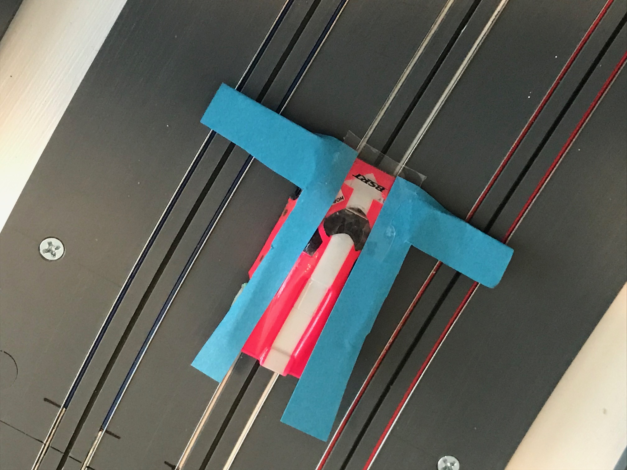
Magic Raceway's Test Car
For a dead strip installation, the lap counter system is tested by taping over more and more of the dead strip rails until the lap counter becomes unreliable. Like the optical system test the car is driven as fast as possible. I start by taping half of the length of the dead strip over. I start taping from the end of the dead strip working toward the beginning of the dead strip to check if pickup bounce was causing a problem. I would then run the fastest car I had over the counter for a minimum of 20 laps in each lane. If all laps are detected, I consider the system to be reliable. I would then repeat the test with more and more of the dead strip taped over until the system became unreliable. The last successful test provides the minimum update time (or distance) required for the system to operate. I would then run a separate test where the center half of the dead strip was taped over to verify that the system did not double count. This second test was done at various speeds. At the end of the second test the car is going around at a speed that just allows it to coast across the dead strip without stopping.
With a dead strip an important item to look for is the transition from the track rails to the dead strip section rails. You don’t want the pickups to bounce over this transition as this can lead to problems. Floating pickups do not provide an input signal to the lap counter. Likewise, bouncing pickups shorten and reduce the quality of the signal provided to the lap counter.
Unfortunately the dead strip method only tests one lane. This is fine if each lane has its own dedicated counter circuit. If the dead strip interfaces with an RMS such as Trakmate or Slottrak you need additional testing to ensure that there are no scanning issues. This additional test simultaneously tests all lanes. Such a test either requires for (or six) extremely good drivers or an external circuit that triggers all lanes simultaneously. I haven’t used a dead strip for 20 years and have not had to build such a circuit. If I did I would probably use a 555 chip with a fixed simulated lap time and an adjustable dead strip trigger signal time. I would then test all of the lanes simultaneously shortening the trigger signal time until the system became unreliable. I would then work backwards from my last good test to calculate how long the dead strip would have to be to provide a signal with the same time duration. I would then determine how much margin was available. I would still do the above tests to check for pickup bouncing and double counts.
The purpose of these tests is to determine for is how much of a time (or distance) margin exists between the time required for the car to pass through the detector and the last successful test. For example with the Magic Raceway test car I have a safety factor of five as the wings are one fifth the length of the car. With a dead strip that operates successfully with 80% of its length taped off the safety factor would also be five. I want my lap counter systems to have a minimum safety factor of three when all lanes are triggered simultaneously. Obviously, I am quite happy with a safety factor of five.
What about tracks that use other detection methods such as reed switches, hall effect sensors, micro-switches embedded in the slot or web cameras? In my opinion there is no way to determine how much of a safety factor these systems have as they either work or they fail. There is no way to tape off or trick the sensor to determine if it would count a significantly faster car than the one that is being used to test the system. The problems with reed switch based systems are legion and I have seen enough reed switch systems fail that I do not consider them reliable. I have only seen one track that used a hall-effect sensor. It seemed fine but then again my car was the only car on the track. As with reed switch systems I would be concerned with the car on an adjacent lane causing interference and possibly false counts with a track using hall effect sensors. While I know that they exist I have never seen a track that uses micro-switches to sense the cars guide pin passing by. The results of a test I did Beta testing a web camera as a lap counter wasn't pretty.
There are those who kluge together two or more lap counter systems to the same track so that they have a "backup". To me this indicates a lack of testing and trust in either system. If there is a difference in laps at the end of a heat of the race (and no marshal saw what happened) then which lap counter do you trust? Oh, the arguments you could have.
Test your lap counter. You will demonstrate its operability, learn from your experience and you just might identify and resolve a previously undetected problem. Better to find and fix problems during testing as opposed to finding them in the race.
![]()
June 18, 2020