This article shows how to add an inexpensive pulsating audible alarm to your track that will inform the driver, marshals and the race director if power is lost to a lane due to a tripped lane breaker or blown fuse.
Ever have a case where a lane fuse or breaker tripped in the middle of a race and the driver didn’t know it. The breaker or fuse was doing its job and protected the track, car and/or controller from damage but the driver was losing laps tearing his car apart for an easily diagnosed problem. The following circuit provides a pulsating audible alarm when track power is on and a lane fuse blows or lane breaker trips. As the alarm is powered from the track it resets when track power goes off. The pulsating tone is distinctive and loud enough to be heard by the drivers, marshals and race director. If power to a lane fails during a race, the alarm will automatically alert the race director who can turn the track off, correct the problem, replace the fuse or reset the breaker and restart the race with only a minor interruption and more importantly without a driver going ballistic.
Wouldn’t a power indicating light at each driver’s station do the same job? In my opinion, the audible alarm is superior. Indicating lights burn out and consume precious track power that is best provided to the cars and controllers. There is also the human factors question that 1) The driver knows that a track power light exists, 2) Looks at the light when his car stops and 3) Knows what the light is telling him. The driver still has to communicate with the race director to get the breaker reset. The audible alarm immediately alerts ALL of the drivers, marshals and the race director when the incident occurs allowing corrective action to be taken immediately. Indicating lights are also susceptible to physical damage from controllers, parts and/or stuff at the drivers’ station. All of the parts in this system are under the table and protected.
A 10 Amp regulated power supply can continuously supply a maximum of 180 Watts of power at 18VDC. The power consumed by a 4-lane alarm system when the track is on is approximately 0.04 Amps @ 18VDC or 0.7 Watts. This is less than 12% of the power consumed by a single 6 Watt indicating lamp or less than 3% of the power consumed by four indicating lamps. The 1,700 Ohm resistor across each lane’s power supply is too small to be noticed by the driver or car and will not impact car, controller or track performance.
The circuit shown below is easy to build, reliable and best of all inexpensive. The parts for the 4-lane system installed at CRR were normal stock items obtained from a local Radio Shack for about $8.00. The alarm is a better system that consumes less power for about the same cost as individual lane power indicating lights.
Schematic for a 2-Lane Audible Fuse/Breaker Alarm
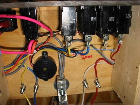
T
he following image shows the audible alarm system as installed at CRR’s power control center. The round black object at the lower center of the photo is the 3-28VDC piezoelectric transducer that emits the pulsating alarm tone when one of the four lane breakers trip. The blocking diodes are connected to the bottom of each lane breaker. Look for the small black devices with a silver stripe at the breakers top terminal (Hint: Follow the small blue wire) . The resistors are connected from the Black to the Red terminals at each driver’s station and are not shown. As designed, the system requires a minimum voltage of 14VDC. The lower operating limit can be extended downward by reducing the value of the dropping resistor. Replacing the 1,700 Ohm resistor with a 1,000 Ohm resistor would reduce the lower limit to less than 12VDC which would make the alarm suitable for the larger scales as well. The transducers 28VDC maximum limit establishes the systems maximum operating voltage.
4-Lane Audible Fuse/Breaker Alarm as Installed at CRR
The above system is based on a similar alarm system installed on a Bucktrax Banzai in 1994. The earlier system used the same transducer and to my knowledge this system has never failed or caused a problem. The CRR design revised the earlier design to add the dropping resistors at each lane. This revision ensures that the alarm is not dependant on the car being on the track to complete the circuit.
I recommend that suitable protective devices (10A fuses or 6A breakers) be installed to protect every lane of every track from damage in the event of an overload. I also recommend that either a lane power monitor or a lane power failure alarm like the one shown here be installed on every track. The power failure alarm as described above is another little thing that helps to make a good track great.