The
drivers station is more about human factors or the man-machine interface than
anything else. The drivers station
needs to have a place to hook up the controller, indicate to the driver what
lane they are hooking up to and ideally tell the driver track power status
(on/off) and where to go to next when the segment is over.
There are as many ways of creating a driver’s station, as there are
slot car tracks. The drivers
stations at CRR use a combination of ideas obtained from different tracks that
were combined into what is described here.
The
drivers station is the place where the drivers hook up their controller and
place their pit box. A pit box
contains oil, tape, spare parts and tools deemed necessary by the racer for
quick emergency repairs and maintenance during a race.
Pit boxes come in all shapes and sizes.
My drivers stations are on a flat ¾” thick plywood shelf without
dividers. The shelf is
approximately ten inches deep and can accommodate a reasonably sized pit box.
The shelf is well braced and can support a considerable amount of
weight. A young adult could
probably stand on it. Controllers
connect to the track via #10/32 machine screws coming up through the
shelf. The screws use fender
washers on top and bottom and a lockwasher.
The wires are soldered to the lower fender washer.
The fender washers reinforce the plywood and the fender washers visible
to the driver are painted red, white or black to designate the post color.
The upper fender washers were recently replaced with similar washers made from
Formica. Like the fender washers the Formica washers are painted red,
white and black. The advantage is that the Formica washers do not
conduct electricity. This system is simple, rugged and, so far, bulletproof.
Some
have used small gauge pipe (approximately 3/8” in diameter) for the posts.
Some have hidden the posts in large diameter holes drilled into the
sides of the table. The ends of
the posts are flush with the side of the table and inside of the hole is
painted the wire color. Nice, but
unfortunately I don’t have photos of these types of installations.
I have also seen tracks where the drivers station uses a plastic handy
box. The handy box is usually
painted ABS plastic and the box could fail if an angry driver either rips the
controller wires off of the posts or takes his aggression out on the driver
station with the controller. In
twenty plus years of racing I have seen both happen.
At CRR the angry drivers hand and controller will be second rate but
the drivers station will be fine. That
might not be the case if an ABS box is used without reinforcement.
The other thing that the handy box does is hide the wiring.
Nice, but difficult to troubleshoot quickly.
Slot car track wiring is usually exposed.
With neat, well-labeled, color coded, exposed wiring, problems are easy
to diagnose and fix quickly in the middle of a race.
With the low voltages involved (18-20 VDC) the exposed wiring is not a
personal safety issue.
The
Bucktrak and Brystal tracks use a prefabricated panel for the drivers station.
This panel is the lane color and uses banana plugs for the controller
interface. This offers a bit of
flexibility as the controller can either clip on or use the banana plug
interface. I carry adapters and
convert my controller clips to banana plug operation when I get to a track
with this type of panel.
One
thing I do not recommend or install is a ¼” diameter stereo phone plug for
the controller. When the phone
plug is being inserted or removed it temporarily shorts out the tracks power
system. If battery power is used
and the plug jams while being removed (usually in anger) while the track is on
the results can be spectacular! Ever
see a power relay or switch go up in smoke?
I did when the plug jammed while being ripped out while the track was
at power. Thankfully the switch
self destructed all over the room before the track wiring melted or worse
happened. I think that’s enough
about ¼” diameter phone plugs.
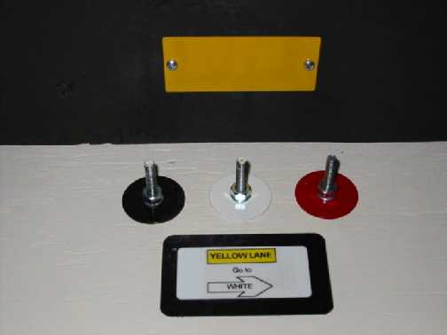
The lane information provided to the driver is critical. At CRR two means are provided to identify lanes to the racers. The first is a vertical plate mounted above the posts. This plate is painted the same color as the lane. The second is mounted on the horizontal shelf in front of the posts and tells the driver what lane he is in and where to rotate to for the next heat. The second plate uses both colors and words to convey this information. The next heat arrow tells the driver which way to move to rotate to their next lane. I first saw the lane rotation arrow at Brian Lowe’s track at the Western States Race in 97’ and adapted the idea for CRR. Brian uses custom engraved and painted panels. I used industrial grade self-laminating adhesive identification tags manufactured by Electromark. Less expensive but they appear to be just as durable and just as effective.
At CRR green and red LEDs are positioned across the main straight from the drivers and provide an easy means of determining if power is on or off without distracting the driver. The LEDs are not high intensity but convey the required information without distraction. Bright power status lights can and have distracted drivers. CRR’s audible tripped breaker alarm allows for easy troubleshooting of problems, alerts the drivers if a breaker is tripped and protects the controller and track in the event someone hooks up wrong. If a breaker trips during a race “track” is called and the problem corrected before the race is allowed to continue. In three years of racing the breakers have tripped in practice but rarely under race conditions. In just about every case the breaker opened because the controller was hooked up backwards.
CRR’s
reversing switches, relays and circuit breakers are mounted below the table
and are not normally accessible to the drivers.
The reversing switches reverse power after the controller so the
controller wiring remains positive gate at all times.
Positive gate means that the White post is connected to the positive side of the
power supply and the Red post is connected
to the negative side of the supply. Wires
from the Red and Black posts are connected to the track or to the reversing
switches and then the track.
Track
call buttons can be mounted on the driver’s stations.
If track call buttons are installed near the driver’s stations they
should be shielded from inadvertent operation by a collar. The collar was
made from a 1-1/2” white PVC pipe cap and does a fine job of shielding the
button from stray fingers, controllers or pit boxes while allowing easy access
to the button when required. CRR
has three track buttons. The one
mounted on the driver’s station is shielded.
The remaining two, table mounted, buttons are bright red and easy to
find but are not located in areas where they could be inadvertently actuated
and, so far, have not caused a false track call.
All three pushbuttons are interlocked with the track power relay so
that they can only shut down the track when pushed.
The interlock prevents the track buttons from ending the track call and
restoring power. Following a track
call, power can only be restored by the race director and not by anyone
located at the track.
The drivers station is the slot car tracks man-machine interface. Hopefully, the above has given you some ideas for creating yours.
Revised March 2012