Siberia Racing Tech Pages
HO Controller History From 1960 to Tomorrow
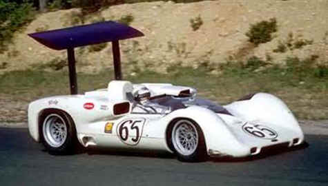
The Chaparral 2E – Inspiration for Innovation.
This first began as a reply to a comment made to me in an e-mail several years ago. The thoughts grew and evolved to what is here. It is a documentation of HO controller history starting with the introduction of the Aurora Thunderjet 500 in the 1960s and concluding in what we could see on the market as early as tomorrow.
HO scale controller modifications most probably began immediately after Aurora introduced the Thunderjet-500 in 1963 with the steering wheel controller. While Aurora, Tyco and others introduced various home set controllers, the first big thing in HO controller development was the introduction of the Ruskitt (i.e. Parma) pistol grip controller. Various ohm resistor barrels (i.e. 90 Ohm, 45 Ohm, 25 Ohm, 10 Ohm etc.) were available for the Ruskitt controller and changing barrels was the extent of development for some time.
Like the Can-Am HO in the 70s and early 80s was a single class unlimited series. There was one class of car and almost anything was legal. In response to the car technology explosion an HO controller technology explosion occurred starting in the late 70s and ending in the mid 80s. I was racing with Indiana, Illinois and Michigan HOPRA during this time and was involved with and contributed to this explosion. In this short time period variable resistance, variable brake, coast and in-line resistance (a.k.a. choke) was developed and perfected. Controllers were being modified between and sometimes at each race to add or refine concepts that might provide an advantage. I had all of the above and at least one additional trick built into my Ruskitt/Parma resistor based controllers when I won the HOPRA National Modified and Restricted Open championships in 1987. These concepts continue to be used today and have been adapted for use with electronic (i.e. transistorized) controllers. Most of these concepts can be found on my “Variable Controllers - Getting the Most out the Parma's Sebring or Turbo Controller” tech page.
The diode based “Omni” controller was developed during this time. It was clean sheet of paper approach and an attempt to minimize the number of controllers required to race various classes as each class required a different ohm controller. This required racers to carry three or four fully tricked out controllers to each race. The Omni controller featured a number of diodes connected in series and wired to a wiper block. The trigger controlled how many diodes were inserted into the circuit. Each diode inserted into the circuit reduced voltage applied to the track by approximately 0.7V. The range of the controller could be adjusted by inserting or cutting out diodes in the control circuit via selector switches.
Analog transistorized controllers followed. These eliminated the need to carry multiple controllers to race different classes. The early units were adopted from 1/24th controllers and it took time to adapt the 1/24th controller for HO use. While transistorized and diode based electronic controllers have been around since the 1970s they didn’t seriously take hold in HO until the late 1980s. While some consider discrete diode based controllers as electronic this document does not. This document considers electronic controllers as devices that vary voltage to the armature of a slot car by use of a transistor operating in an analog (as opposed to a switching) mode. Switching or PWM controllers are discussed separately as “programmable” controllers.
The Author’s Racing and Electronic Controller History
I started racing T-jets in the 1960s. I have won HOPRA championships in Indiana, Iowa and Michigan. I won the HOPRA Restricted Open and Modified National Championships in 1987. This was followed up by winning the HOPRA Winter-National championship the following year. I retired from professional racing in 1991. I was reintroduced to racing in 2001 and since then have won several NITRO and MSRA championships. I am currently not racing in any series but will participate at the occasional sprint or endurance race if it tickles my fancy. One of my notable achievements was to influence the design of the G3 chassis after the original prototype chassis were tested and the design approved. This influence added the “front bumper” to the G3 chassis that protects the pickups and reinforces the nose of the chassis.
I am employed as an Electrical Engineer and developed and sold the widely acclaimed line of MaDD Bodies and the M-Magic controller. I have inspected, repaired and/or modified HO scale electronic controllers made by Ruddock, Scale-Auto, DiFalco, Lucky Bob, Theisen, Mullen, Jay-Gee, Trek, Go-Go, Moonstone, BRP and others.
I purchased my first electronic controller in 1995. I purchased my first “wiperless” electronic controller in 2005. Problems surfaced soon after the “wiperless” controller arrived. I like to tinker and rather than returning it, out came fiberglass sheet, switches, resistors other miscellaneous parts and wire. The result was a highly modified and improved version of this “wiperless” controller. When complete it had an “unbreakable” fiberglass frame, improved sensitivity, variable brakes and coast.
The Modified Wiperless Controller
I used the improved “wiperless” controller at home and carried it in my pit box but didn’t race it or think all that much of it until the last NITRO T-Jet race of the 2005/06 season. I had a schedule conflict and couldn’t race but I had to stop in. When I arrived, the drivers for the final Superstock (i.e. Skinny Tire) class qualifying heat race were finishing their warm-up laps and were getting ready to race. There were two open lanes in this race and I asked if I could keep the drivers company. I got the nod, pulled out a car and hooked up the “wiperless” controller. Without practice or setup I took the overall lead in the third segment and ended up as top qualifier. I really hated to leave after that. Until then I had not realized how easy it was to dial the controller in and how effortless the car was to drive with the modified controller. I also realized that this “wiperless” controller was worth further development. The end result of this development was the M-Magic controller.
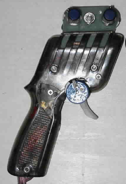
The first M-Magic controller with an updated transistor and considerable revisions to both the power and control circuits was made early in the summer of 2006. Between then and now over 50 M-Magic controllers have been built. My primary controller is M-Magic #005 that was built in late 2006. In mid 2007 the dual range option was introduced as the single range controller did not have enough range to accommodate cars running at 18V and 12V. While the dual range option is the most visible change the controller has gone through a significant number of improvements. M-Magic #005 has seen them all along with a few unique modifications as I continue to experiment and tweak the design.
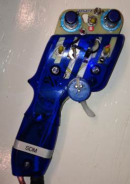
Maddman’s M-Magic #005 Controller
M-Magic commercial production ended as it became all consuming and again I had to decide between family, the day job or slot car racing. As with MaDD Products, this decision resulted in controller production being significantly rolled back. Unlike MaDD Products I did not sell the M-Magic license and design. A few M-Magic controllers have trickled out annually since this decision was made. I also continue to maintain, repair and upgrade the fleet of M-Magic controllers produced.
So much for history. Let’s discuss some topics associated with controller design and construction.
Transistor Ratings
The transistors size and rating is important. The following figure shows the three sizes of power transistors used in HO controllers approximately to scale. The transistor on the right is continuously rated at less than 1-Amp. The other two have continuous ratings of 20-Amps or more. With a suitable sized heat sink their continuous power dissipation is 1-Watt, 125-Watts and 160-Watts respectively. Without a heat sink their continuous power dissipation is significantly less. The transistors peak current withstand time current rating must be significantly greater than the rating of its protective device or the transistor will fail first and protect the fuse. There is also a difference between the transistors peak and continuous ratings. The peak rating is significantly greater than the continuous rating. The types of transistors shown below are all used in controllers that are sold for approximately $300. The cost difference between the transistor types is not significant and they can all be made to work with cars from T-Jet to Unlimited. Which transistor would you want in your controller?
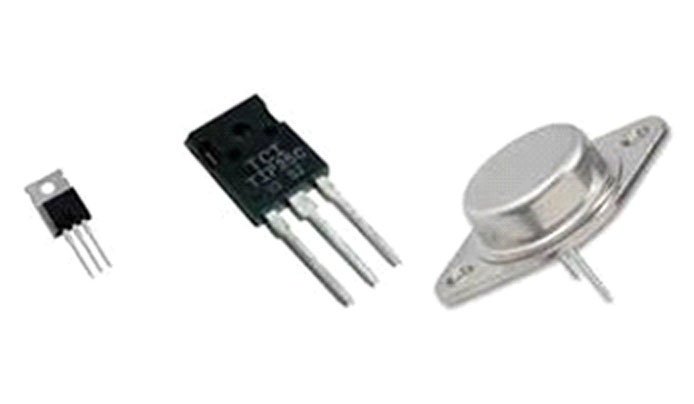
1-Amp and 20-Amp Power Transistors
Size is important. However, size is not everything. The first M-Magic controllers used a 15-Amp rated transistor with a case that was rated at 160-Watts. Unfortunately the transistor’s protective curve did not coordinate with the fuses melting curve. As described in the next section, the fuse failed to protect the transistor.
Short Current Protection
Protection against overloads and short circuit current should be mandatory for any slot car controller but especially for an HO controller. T-Jet and AFX pickups short the rails when a car spins. Mistakes can happen when hooking up. Front axles have come apart scattering parts all over the track. During practice tools, parts and the occasional soda car have ended up across the rails. When a short circuit occurs without proper overcurrent protection something will eventually open the circuit to clear the short. I have seen improperly protected track, track wiring and power supplies damaged as a result of a short. As a result of short circuits I have seen blown fuses, tripped breakers, failed power relays, melted wires, smoking wires, melted track, red hot track rail, exploded power switches, a welded in (half pulled out) ¼ inch stereo controller plug. In one memorable case another vendor’s transistorized controller literally exploded when power came on. The transistor in that controller failed spectacularly with sparks, smoke and flames!
The M-Magic has overcurrent protective devices built into the transistor power circuit, control circuit and the brake/coast circuit. The most obvious is the replaceable fast acting fuse that hangs below the controller. There are two thermal trip, automatic resetting, solid state circuit breakers contained within the controller handle.
I have personally experienced the M-Magic’s protection. I have failed the controller’s fuse by hooking up backwards. Some wildly sideways moments with a T-Jet also resulted in fuses failing. The standard M-Magic has a 5-Amp fast acting automotive fuse. When these events occurred my controllers have had up to 15-Amp fast acting fuses installed. In all cases I replaced the fuse and kept on going. I have also hooked up incorrectly with no fuse or controller failure. While the protection provided may not be adequate in all cases, this operating experience demonstrates the level of protection provided by the design. Very few M-Magic controllers have required transistor replacement. I continue to be amazed that transistorized HO controllers without short circuit protection continue to be developed and marketed.
I know that a lower rated transistor or a controller without some of the M-Magic’s protective features would have failed. The first generation M-Magic controllers had a 15-Amp rated transistor that was protected by a fast acting 5-Amp fuse. When a T-Jet went sideways in a race causing a short, the transistor failed to protect the fuse. This type of failure is not unusual if the fuse is not properly sized as fuses open in an I2t time-current relationship. If sufficient current is available a shorted transistor will extremely quickly and must be protected by a fast acting fuse having a lower continuous rating. I don’t know how but the driver kept on racing and burned out the trigger pot. The five M-Magic controllers using that power transistor and trigger pot design were recalled and modified at my expense to revise the control circuit and to install a higher quality transistor with a higher rating. Testing and operational experience shows that now the 5-Amp fast acting fuse fully protects the uprated transistor.
Through experiences like the above I have found is that a ratio of 5/1 between the transistor and fuse ratings is a good rule. In other words, protect a 15-Amp rated transistor with a fast acting fuse rated at 3 amps or less. Use of a lower ratio, a time delay fuse or a thermal circuit breaker comes with increased risk unless you have reviewed the over current device’s time current curves against the transistor’s published current damage curve and have verified that the fuse curve is fully coordinated with the transistor damage curve.
Metal controller frames and heat sinks can be electrically live and bumping one of the three controller posts with a metallic part of the controller frame or the heat sink has resulted in lost races as a result of shorts and resultant failures.
Controller Heat and Temperature
Another issue to consider is heat and temperature. I have found that if the transistor is properly sized and provided with a properly sized heat sink, power transistor temperature is not significant. At full throttle or when braking the transistor is not working and no heat is generated. Heat is generated during the time spent at part throttle. Assuming the controller is adjusted properly and the car is driven hard, the time the transistor generates heat vs. the total operating time is between 30-40%.
The other factor that creates heat is current. HO cars do not draw the running current that some assume. Measurements indicate that running cars draw between 10% and 30% of the calculated current draw based on cold armature resistance. This is consistent with DC motor theory but widely ignored by most who “calculate” HO armature running current.
For example, at a race with four G-Jet cars with 9-Ohm motors and the power supply set at 12 VDC the measured running current provided by the power supply was approximately one (1) amp. The calculated current should have been 4 cars x 12 VDC / 9 Ohms = 5.3 Amps.
Heat generated by a transistor is proportional to the square of the current. This is illustrated by the following. In this graph current is the blue line. Heat (current squared) is illustrated by the red line.
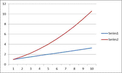
Heat vs. Current
The running cars required less than 20% of the predicted current and an 80% reduction in current results in 1/(5 x 5) = 4% of the heat projected. In another test a high speed recorder measured an unlimited car’s motor current at approximately 60 Amps for one millisecond when the power came on. After this initial surge, the current readings stayed below one (1) amp while the car was running. An unlimited cars motor resistance is less than one ohm. Assuming a one ohm motor at 18 Volts an unlimited car should draw 18 Amps. The heat associated with the running current measured was 1/(18 x 18) = 0.3% of the predicted value. The above stall current calculations ignore the effect of track wiring or contact resistance. While this is standard practice it is also incorrect as resistance anywhere between the power supply terminals and the motor will reduce the current draw of the motor.
Heat sinks transfer heat from the transistor to a cooling medium such as air. Without a heat sink the transistor case temperature can rise to levels that can result in burns or transistor failure. With the exception of the BRP, GoGo, Moonstone, Trek and M-Magic all of the HO scale electronic controllers mentioned above mount their heat sink external to the controller. The BRP heatsink is minimal. The Trek, GoGo and Moonstone controllers have no heat sink and their transistors become hot to the touch after driving a HOPRA superstock car around for a few laps. The Trek controller uses a plastic frame and discoloration and localized melting of the frame has been observed as a result of heat generated by its power transistor. The other controllers mentioned use higher current rated transistors which have a larger footprint and use a suitable heat sink and, as a result, transistor temperature is effectively a non issue.
The prototype M-Magic controller was tested with T-Jet, Super Stock, Polymer-Modified and six-magnet Unlimited HO cars to determine the effectiveness of the design and to determine the transistor and heat sink operating temperatures. Measured peak transistor temperature during these tests remained under 120°F. The measured peak temperature was approximately 30% of the transistor’s published maximum operating temperature. The individual performing the test has other electronic controllers and, in his opinion, the heat generated by the M-Magic was less than the heat generated by the electronics in the handle of his external transistor controller. I subsequently repaired his external transistor controller and I agree with his opinion.
Basic Controller Types
The above discussed controller’s from an engineering perspective. From a driver’s perspective, the most important issue is the response of controller power control circuit. The two basic types of analog transistorized controllers are the two-wire and three-wire designs. Both designs control the transistor using a voltage divider circuit. The difference between the two controller designs is the reference point for the voltage divider. For a three wire controller the reference point is the power supply negative which is the red (i.e. brake) wire. The two wire controller uses the black (i.e. track or motor) wire as its reference point.
Like a conventional “Parma” resistor controller, the two-wire design incorporates the car’s motor as part of the control circuit. The motor generates a voltage when running. This voltage changes with the motors speed and load. The more speed and less load the greater the voltage generated. The generated voltage raises the motor’s resistance as seen by the controller and reduces the motor running current. The change in the motors resistance impacts a two wire control circuit as the controllers reference point is constantly changing with motor speed and load.
As a result of the motor’s influence, a two-wire controller acts much like a conventional resistor controller. When adjusted into its sweet spot a two-wire controller provides a large band of controllability as there is with a conventional resistor controller when the right ohm resistor is used. Outside of this sweet spot a two-wire controller can act like an on-off switch and can be extremely difficult to deal with. What I have learned is that many racers (including myself) set the sensitivity too high. The car is easier to drive and more consistent if the sensitivity is turned down from what at first seems right. The two-wire controllers (white-black with optional red wire) can be used on any track. The Trek, M-Magic, Go-Go, Moonstone and DiFalco controllers are examples of two-wire controllers.
A three wire controller uses the power supply negative (i.e. red or brake) wire as the reference point for the control circuit. As the reference voltage is fixed, the voltage provided to the car will always be the same at a given power supply voltage, trigger position and sensitivity pot position. This design is almost insensitive to motor feedback. Unlike the resistor or two-wire transistorized controller the three wire controller has no “feel” as the transistors control circuit is not impacted by the resistance of the motor or its current requirements. A different driving style is required with a three-wire controller to compensate for the lack of “feel”. The three-wire controllers (white-black-red wire) must have the red wire connected to the brake terminal to operate. This can be a problem as some tracks do not have a brake terminal. When a three wire controllers red wire is disconnected it becomes an On-Off switch. The Ruddock, Theisen, Mullen, Jay-Gee and Lucky-Bob are examples of three wire controllers.
Transistorized Controller Design Failures
Both two wire and three wire controller designs require power to operate. With the two wire design the power to run the controller is only required when the controller is at part throttle. At full throttle the transistor is bypassed and the control circuit requires almost no power. As a result the two wire controller is very efficient. The two wire controller can be built without or with optional brakes and/or coast. Typically they are built with brake and/or coast features. A three wire controller requires power to operate as the reference point of the voltage divider circuit is the red or brake wire. As the brake wire is required the three wire controllers are typically built with adjustable brake and/or coast. At full speed the controller is still consuming power. This is power that is coming from the power supply and could be going to the car.
I have a three-wire controller that is a cousin of the one used during the tests of the prototype M-Magic. With no car on the track the controller draws approximately 0.2 Amps at 19 VDC with its trigger just off the brake band. Near full throttle the same controller draws 1.2 Amps at 19 VDC. These readings were taken with no car on the track and all the power going into the controller. The readings did not change significantly when a car was added. At near full throttle the controller is generating over 20 watts of heat and several of the controllers components were operating well above their ratings. If the trigger is left in the 90-95% position the sensitivity limit resistor will quickly begin to smoke and will eventually cause severe damage to the plastic handle, fiberglass frame and eventually the controller’s wiring.
The damage was caused by the controller being first developed for 1/24th scale cars and 12V use and subsequently adapted to HO. The adaptation did not consider the effect of the increased heat generated by components in the controller as a result of the increase from 12V to 18-20V. Heat is proportional to the square of the voltage and a 150% increase in voltage equates to a 225% increase in heat. The builder either failed to recognize this or made no attempt to reduce the controllers operating current.
The M-Magic’s two wire and the prototype three wire M-Magic control circuits generate less than one watt of heat and no control circuit components run warm to the touch. A significant improvement compared to the above.
One widely used two-wire HO controller had (and may still have) an error in its control circuit as the transistor’s sensitivity changes when the variable brake pot was adjusted. This wiring error is passed down from the same manufacturers 1/24th scale controller. Because a 1/24th scale controller uses a three to five ohm brake pot the issue only became obvious when the controller was adapted for HO scale and the brake pot resistance was increased to approximately one hundred ohms. Since the controller’s designer does not race HO, the issue remained undetected. This particular error was subsequently copied by at least one other designer into their 1/24th scale controller. This designer subsequently adapted the 1/24th controller for the HO market without correcting the error.
The trigger on a wiperless controller is connected to a potentiometer (pot) as opposed to a wiper riding on an external resistor. The method of securing the wiper to the pot’s shaft and the pot to the controller frame are critical. If the trigger is connected to the pot shaft via a screw in the narrow part of the trigger then the trigger will eventually break at that point. The trigger screw should be secured to the pot shaft in a way that the shaft can not rotate independently of the trigger. The trigger pot must be secured to the fame such that it cannot rotate with respect to the frame. None are perfect but the M-Magic and the Lucky Bob are the best at trigger pot and trigger position control. The Lucky Bob uses a 4-40 screw to lock the trigger to the shaft. On the surface the M-Magic design looks weaker as it uses a 2-56 screw as a trigger lock. In fact the Magic design is more positive and more robust. When the trigger goes out of calibration it’s typically because the pot has rotated with respect to the frame. The fix simply rotates the pot back to the correct position.
One advantage the Parma Turbo based controllers have is that the frame forms a natural trigger full power backstop. This minimizes the probability that the trigger from being overstressed and failing when it is taken to full throttle. The backstop should stop trigger movement just after the trigger wiper hits the full power stud. The backstop sounds like a great idea but is a double edged sword. All of the Turbo frame based controllers (and the Lucky Bob controllers) that I have repaired have had the full power stop set such that the trigger was not making contact with the fixed contact when fully depressed. As a result full power wasn’t getting to the car when the trigger was fully depressed. With one exception, no M-Magic triggers have broken over the operating history of the controller. To provide additional protection I have added a trigger backstop to that owner’s M-Magic and Trek controllers.
New problems can be created (or old problems re-invented) when an existing controller design is copied. In the first quarter of 2013 I had the chance to examine the first known M-Magic “copy-cat” controller. From a quick visual inspection the “clone” looks impressive. The graphics are bold and catch the eye. On the surface it’s an acceptable attempt. Look deeper and you will see no overcurrent protection, the heat sink is effectively non-existent and the trigger setscrew is located in the weakest spot of the trigger. It had more problems but the above is enough for now. Considering that I know where most of the controller’s electronic components were sourced I would speculate that the power transistor is undersized and not protected by the fuse installed. These issues were all resolved during the design and evolution of the M-Magic. I pointed out some of the more significant issues to the controller’s owner and recommended that the “clone” be returned to the builder to address some of the more serious deficiencies. I would not buy this controller and neither should you.
In the last year or so a controller manufacturer announced a new “mid-range choke” feature. This feature adds an adjustable voltage step between the last band and full throttle. A second manufacturer recently announced a similar feature. Sorry, but nothing is new. A bit of digging discovered a 2009 on-line article for a transistor controller that clearly shows the “mid-range choke” feature. It’s a simple adaptation as the modification inserts a variable resistor in the transistors control circuit. It appears that if the sensitivity is turned down the M-Magic does this naturally.
In 2013 I modified my backup controller and experimented with adjustable “torque control” at the Nuvolari Enduro. It was difficult to adjust and in my opinion the ability to adjust the “torque control” value did not offer a significant improvement. I abandoned this controller and used M-Magic #005 for qualifying and the race. I do not remember if it had a simplified (i.e non adjustable) version of the “torque control” circuit installed. Today, a simplified, non-adjustable, version of the “torque control” enhancement is now installed on my two M-Magic controllers.
In 2014 I began experimenting with Field Effect Transistors (FETs). Incorporation of FETs into the M-Magic design could possibly improve full power bypass and brakes. Incorporation of FETs into the Magic’s design would complicate the circuit and would require deletion of the polarity switch. It would also require that the brake wire be connected at all times as the FET circuit needs a solid negative reference point. In my opinion the deletion of the polarity switch and the requirement to have the brake wire connected at all times makes the controller less flexible to the user. At this time the FET has not shown a significant improvement providing that the controller is properly maintained.
My controller design philosophy is KISS. If I don’t see a significant advantage then the average racer most probably will not see it either. In my opinion there is no point in adding a feature that is not cost effective to me or the controller’s user.
Caveat emptor “let the buyer beware” defines the slot car controller market. There is a lot of advertising and possibly unsupported claims out there. Careful navigation of the waters is required to select the proper controller. Hopefully the above sheds some light on issues to be considered before buying an electronic controller.
Your Decision – Two or Three Wire?
Earlier, I discussed the two basic transistorized controller types. These are the two wire and the three wire design. Is the two wire controller better than the three wire controller or is the reverse true? This question can only be answered by the individual racer. If you race on tracks without a brake wire connection then the decision is made for you and you have to use a two-wire controller. If not, then the choice is dependent on your driving style and preference. I have built both two and three wire versions of the M-Magic. I prefer the two wire controller and use it exclusively. I have used a three wire controller on rare occasions. In retrospect I wonder if those choices to use the three wire controller were mistakes. The three wire controller can serve up faster lap times. Unfortunately the three wire controller also offers up more chances for lost time due to driver error. The two wire controller is more consistent lap after lap and for me the better choice.
It is possible to convert a three-wire transistor controller to a two-wire design and vice versa. However, this conversion is not something that is done by just moving a wire or installing a switch. Along with the required wiring changes the two controller types require different bias resistors and sensitivity potentiometers and cannot share these components.
Programmable Controllers
Up to now I have not discussed digital or programmable controllers. Several years ago I took part in a discussion with a number of racers after the first race in which we saw a programmable controller in use. This controller was a one-off design and was quite impressive. The group’s consensus was that the design of a programmable controller is limited only by the programmer’s imagination. Several college engineering projects have developed smart programmable controllers. These smart controllers have “learned” to drive a slot car around a track without a driver. In my opinion a programmable controller can easily be developed to offer advantages such as true coast (i.e. anti-stall), automatic brakes, automatic choke, reduced full voltage or a discrete voltage step (or ramp) between last band and full throttle, custom acceleration and decoration ramps and true traction control. Some of these features have been advertised in 1/32nd scale controllers. Fortunately, this technology has not yet been advertised, adapted or mass marketed for the HO market.
Along with the advantages, programmable controllers can also introduce new problems. A commercially available HO programmable and FET Based controller using pulse-width- modulation (PWM) technology in both the power and brake circuits was repeatedly accused of interfering with other resistor and transistor based controllers connected to the same track. The USRA (the 1/24th professional slot racing organization) appears to have agreed with these accusations and the last version of the controller as advertised on-line used a modified version of the programmable controller board. On this controller the FETs appear to have been replaced by an analog power transistor with heat sink and a blast relay. The manufacturer’s website is no longer on-line and it is unknown if either the controller is still in production. While it’s unfortunate that the designer may have thrown in the towel I am glad for the hobby’s sake that the concepts used in this programmable controller were not fully developed and perfected
It is my opinion that, when taken to their extreme, programmable controllers blow the door off Pandora’s Box. If perfected versions of these controllers enter the HO market, racers will be forced to the programmable digital option to remain competitive. Cost is the first issue. Besides the increased up-front cost, these more complex controllers are more susceptible to damage. They will also cost more to maintain and repair as they cannot be repaired by the average racer or the current crop of controller manufacturers. I firmly believe that for the good of the hobby only analog based resistor, diode or transistorized controllers should be allowed and all forms of digital or programmable controllers should be banned along with all use of PWM technology. I have expressed this concern to the HOPRA national director who expressed my concern to the senate. So far, the senate’s opinion is that the current rule which states “Only the track power may be used to power the cars” adequately protects the hobby. I disagree as the rule is too broad and is ambiguous. The words may, could, and should allow interpretation. The words must, shall or “will” are better choices as the intent is to be definitive.
Resistor Only Controllers - One Final Opinion
Unlike some groups I see no need to limit controllers to resistor only technology (i.e. Only stock original equipment Parma controllers with no adjustments, bells or whistles). The idea to limit controllers to stock resistor based Parma controllers appears to be based on the assumption that such a decision reduces cost. In my opinion this assumption is false. The reality is that such a decision can actually increase cost as controllers with different resistor values are typically required for different classes. A stock Parma Turbo controller costs about $50. With options such as larger lead wire, variable brakes, in-line resistance and variable first band resistance the price of the controller can easily exceed $100 in parts and over $200 if you buy the controller fully assembled from a third party.
If you race multiple classes and have multiple controllers it doesn’t take long to raise the controller price to the point where one adjustable transistorized controller is the less expensive and the better all around choice. One controller for all HO car types also allows use of a smaller pit-box for races away from home further reducing cost. Prior to the purchase of my first transistorized controller I used to carry five controller handles and one interface box around that performed the in-line, brake/coast and variable first band resistance. I now pack one or two M-Magic controllers. As a result my pit box has shrunk by approximately 50%. Easier on the body and the pocketbook.
Do It Yourself?
While it all sounds scary a transistorized controller is not difficult to build. A great resource for a two-wire controller design is found on the British Slot Car Association controller tech page should you want to build your own. This resource can be found at http://www.slotcar.org.uk/control/index.htm. This is one of the resources I used when I developed my first transistorized controller.
The above article is for a negative gate track. For these tracks the white wire is negative and the red wire is positive. The HO standard is positive gate and a NPN power transistor is required. I also recommend protecting the transistor with a 1-amp fast acting fuse until you get it working. Once you get it working you can increase the fuse rating to a maximum of one fifth of the transistors constant power rating..
The easiest way to start is to get the power transistor control circuit working on the bench before trying to package it into a controller handle. The Lucky Bob and M-Magic frames are non-conductive composite sheet. Fiberglass sheet is readily available, non-conductive, light, easy to use and almost unbreakable. I recommend Fiberglass sheet over either a metal or plastic frame. If you go “wiperless” you will need to install a microswitch or some other method to turn off the transistor when the trigger is in the brake position.
You may have some problems and fail some components but with patience and practice anyone can do it. Once the power circuit is up and running then you can start to modify your basic power circuit to add brake, coast and other features such as dual range, full power choke, mid-range choke, traction control, FET or relay full power bypass and variable brake designs of various types. It’s all been done before and it’s all available on-line if you dig deep enough.
Regards
Steve “MaDDman” Medanic
January 15, 2015
Note: No part of this document may be used, reproduced or copied without the author’s written permission.