What’s the
weak link in your track wiring? Poor
connections? Small gauge wire?
Undersized power relay? For a
typical track the weak link is the interface between the under track wiring and
the rails. That is typically where
the smallest wire is used and the connections are the weakest both mechanically
and electrically. The quantity and
quality of the jumpers is probably where the most important gains can be made in
track power quality. This article
will look at jumper construction, jumper location and quantity and, for those
with sectional track, how to jumper those pesky track joints for near continuous
rail power.
Track power
jumpers typically use 16 AWG stranded copper wire to connect the main power
leads to the track rails. Smaller
wire can be used; however, the resistance increases if smaller wire is used.
Jumpers using thicker wire (e.g. 14 AWG can be done with care however
they are not recommended. The
problem with the thicker wire is its lack of flexibility.
This lack of flexibility can lead to failure of the jumper over time.
To make a
jumper the underside of the rails is first exposed using a Dremel and a grinding
tool. I like to have at least ¼”
of contact between the jumper and the rail.
A smaller contact area is possible; however, the joints mechanical
strength is reduced as the length is decreased.
The track is then placed on a damp towel and the rails tinned.
After the rails are tinned, trim the jumper lead and tin it as well.
After the jumper is tinned; the jumper is placed in contact with the rail
and heat is applied. In a second or
two the solder should melt and you are done.
Its that simple!
Tinning is
an important step as this step prepares the parts for the final soldering
process. In tinning a light coat of
solder is applied separately to each part to be soldered.
Some folks like to use a low wattage iron or gun for this application.
I use a 30-Watt Weller iron for this work, as it is important to get heat
to the metal quickly to melt the solder and then remove the iron before the
plastic is damaged. A hot, clean
iron is your friend here. I have
also found that the type of solder used makes a big difference.
Poor quality solder may take more heat or time to melt and flow.
This increased heat and time can quickly lead to plastic damage.
The poorer quality solders also may not flow as well and you may need
external flux to get the solder to flow properly.
If you need to use flux, DO NOT
USE ACID FLUX! Likewise, do not use acid core solder!
In time the acid will corrode the wire and/or the rails resulting in
joint failure. Resin flux will not
do this. I have had great luck with
Kester brand solder and use it exclusively.
Thickness of the solder makes a difference too, as the thinner solders
seem to melt easier. For this work I
use a very thin solder (0.031” dia) as its smaller size is an advantage.
The same
technique applies to routed or semi-sectional track.
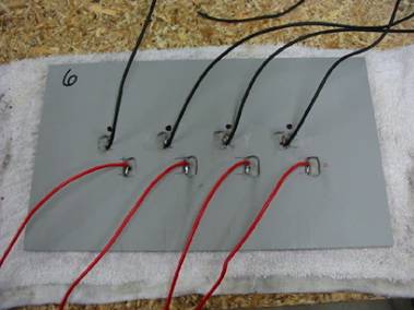
The following photos show jumpers made for my Maxtrax roadcourse.
So far I have made two of these and the design has been used on a second
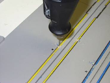
Maxtrax as well. The same technique
as above is used with two exceptions. I
first use a small drill and drill down from the top to locate the rails.
The hole is in the lane color area and is sufficiently small so as to be
almost unnoticeable when the work is done. It
is certainly too small to interfere with an errant guide pin!
The holes were drilled with the track installed as this also locates the
holes to be drilled in the table surface.
The track is
flipped over and a void is ground in the track to expose the rail and the jumper
is soldered to the rail as described above.
Note the damp towel and the “L” in the jumpers to maximize
rail/jumper contact. Careful here as
too much cutting and/or heat can lead to track damage!
The last
step is to fill the void in the plastic using high strength epoxy.
This reinforces the track where it was reduced in thickness and also
reinforces the mechanical connection between jumper and rail.
The edges of the hole are ground in an inverted “V” shape to allow
the epoxy to key itself into the track. That
way I have a good mechanical connection between the epoxy and the track as well
as an adhesive bond. Care is taken
to make sure the epoxy is slightly below the bottom surface.

I route
jumpers through the table using oversized holes.
The oversized holes accommodate the ring-tongue lugs at the terminal
strip end of the jumper and allow the track to expand and contract with
temperature changes without putting stress on the jumpers or the solder joint.
For
sectional track the electrical connection at the joints between track sections
is quirky at best and can be a real pain.
Rust, corrosion, temperature changes
and/or vibration over time can and has caused problems here.
Applying a 20-24 AWG jumper across each track joint virtually eliminates
the voltage drop across the joints and any dead spots.
The technique is the same; however, because of the smaller wire gauge
used things are a bit easier. Unfortunately
the track has to be inverted in sections to apply the jumpers.
I have found that an 8-10 foot section of track is about all that can be
done at a time. Place a jumper at
each end of the section, or in the middle and you will have all the power you
need! Once each section is done,
flip it over and install it as you would regular track.
Instead of the sectional jumpers some have soldered the tabs between
track sections to solve the joint problem. This
fix is not recommended as the track expands and contracts with temperature
changes across the joints and these solder joints can and have eventually failed
due to fatigue. When that happens, a
weak section or a dead spot is usually the result.
For best
results jumpers should be provided every 10 – 12 feet of running length on
sectional track. I found the same
length between jumpers also applies for my Maxtrax.
Because of the smaller gauge and higher resistance per foot compared to
the main power runs, jumpers should be kept as short as possible to minimize
voltage drop. The 16 AWG stranded
wire jumpers on CRR are between 8 and 16 inches in length depending on their
location. The jumpers then connect
to 14 AWG main leads that are routed back to the reversing switches.
This approach has worked very well.
One thing
that CRR does is utilize a separate power return (or negative wire) for each
lane. Some tracks use a common
negative return for all lanes. Electrically
they are the same but since a common return will be simultaneously carrying the
current for all lanes it should be sized accordingly.
If your main leads are 14 AWG then the common return should be 10 AWG for
a four-lane track and 8 AWG for a six-lane track.
These wire sizes are more difficult to work with and therefore the use of
multiple returns is recommended.
A quick note
about protection. A 16 AWG wire will
melt relatively quickly if faulted (shorted) and enough current is available.
If you use batteries or a power supply with a capacity of 20 Amps, or
more, of current then it is essential to protect the jumpers with a separate
fuse, or breaker, for each lane. Recommendations
for protection of a slot car track using fuses or breakers and a design for a
blown fuse / tripped breaker alarm are the subject of a separate Tech-Pages
article.