
Beware the Bear
Siberia Racing Tech Pages
Beware the Bear
![]()
Track Voltage Drop Testing
This is the last in a series of web pages inspired by the building of Magic Raceway. In this page I discuss the importance of designing the track to reduce voltage drop and how to perform a voltage drop test. In the design of the track it is important to locate power taps a reasonable distance from each other. There is an old rule of thumb that power taps located ten feet apart provide acceptable performance. That rule of thumb is at least 50 years old. This rule was probably fine when we were racing T-Jets. Its not so fine for today's high powered high downforce cars.
Ten feet of track between jumpers gives us twenty feet of steel rail to contend with. Steel has a resistance between three and 15 times that of copper. The cross sectional area of a typical Aurora/AFX/Tomy rail is approximately equal to the cross sectional area of #16 AWG wire. When I tested my Viper Scale Racing rail material I found that the rail resistance was approximately 9.7 times that of #16 AWG copper wire. The rail resistance is dependant on the dimensions of the rail and the type of steel used. Your rails may be different so it is important to measure the voltage drop of a sample piece of rail and back calculate resistance. Assuming that your tracks rails have a resistance equal to ten times that of #16 AWG copper wire (i.e. 40 Ohms/1000 ft) the resultant voltage drop of ten feet of track assuming a two amp load would be 2 amps x 2 rails x 10 feet x 40 ohms / 1000 feet = 1.6 Volts. The resultant voltage drop is 1.6V x 100 / 18V = 8.9% of 18 V and in my opinion would be excessive. This value is just for the rail. It does not include the under table wiring, fuses, relays, etc.
This is especially true of sectional track as each track joint adds resistance. Depending on the rail's condition and the tension of the joint the resistance of a single rack joint could be anywhere from 1/50 Ohm to greater than one ohm. Assuming that the ten feet of track has 10 joints per rail and each rail joint has a resistance of 1/25 of an ohm, the voltage drop associated with the joints assuming a two amp load is 2 amps 20 joints x 1/25 Ohms/Joint = 1.6 Volts. The rail resistance and voltage drop remains unchanged at 1.6 Volts and the voltage drop of the 10 foot section increases from 1.6V to 3.2 volts and the total voltage drop is 3.2V x 100 / 18V or 17.8% of 18 Volts. This value does not include the resistance of the under table wiring, fuses, relays, etc.
What is a reasonable voltage drop to design for? Unfortunately nobody really knows and there is no standard. On my last two tracks I used a goal of 3% voltage drop assuming a power supply value of 18 V and a load of two-amps per lane. Why does the acceptance criteria include current? Voltage drop is based on two factors. These are resistance and current. Without specifying a current its impossible to calculate voltage drop. A two amp (2A) was chosen as it is higher than the running curent (amp draw) of all current HOPRA classes from T-Jets to Unlimited. A car may draw more than two amps when accelerating from a stop. However once up to speed the running current drops to one amp or less because of the voltage generated by the armature as it is spinning. This Back EMF lowers the effective resistance of the armature.
The track design process should include preliminary calculations to help determine wire sizes and lengths. Certain factors were included in the design to minimize voltage drop. For example separate positive and negative wires were routed to each lanes power taps and between the drivers stations and the power taps there were no shared current paths. Likewise wire lengths were kept to a minimum. A recommended source for wire resistance values is the National Electric Code. For those who don't have a copy of the code a suitable source can be found on line by searching for the Okonite Cable Engineering Handbook. Its an excellent resource and I have been using this handbook at work and at home since the early 1980s. A portion of the wire resistance table (Table 1-3) from the 2018 edition is shown below.
Okonite Engineering Handbook Wire Resistance Tables for 10-24 AWG Wire
Some things to know about this table are that the resistances given are in Ohms per 1000 feet of wire; annealed uncoated copper is typical copper colored wire that is available at stores such as Ace, Home Depot, Lowe's, Menards and sources such as Graybar Electric. Annealed coated copper wire is copper wire that has been tinned and has a silver color. My track uses uncoated stranded copper wire and, as a result, I used these values. Resistance changes with temperature and I used a temperature of 20C / 68F as the track would be located in an air conditioned basement. I assumed that the wire would remain at room temperature as the currents are low compared to the conductors rated ampacity and as a result the wire's temperature would not change due to current induced heating.
At Magic Raceway the wiring from the power supply to each drivers station panel is #10 AWG copper wire. The wiring from at the drivers station panel to the track jumpers is #14 AWG copper wire. Short leads from the track to each Power Tap terminal block will be #16 AWG copper wire having a maximum length of six inches. Because of the way the power taps are configured each connection will consist of two #16 AWG wires routed in parallel. Two #16 AWG wires connected in parallel have a resistance slightly lower than that of one #14 AWG wire and the jumper length is included in the #14 AWG wire lengths.
The calculations were as follows
Leads from Power Supplies to Drivers Station Panel - 10 feet of #10 AWG @ 6 Amps. 10 feet x 2 wires x 6 Amps x 1.02 Ohms/1000 Feet = 0.122 Volts.
Drivers Station & Wires From Drivers Station to Power Taps - 15 feet of #14 AWG @ 2 Amps. 15 feet x 2 Wires x 2 Amps x 2.57 Ohms/1000 Feet = 0.154 Volts.
Rail Resistance from Power Taps - 6 Feet @ 2 Amps - 6 Feet x 2 Rails x 2 Amps x 40 Ohms/1000 Feet = 0.96 Volts.
Other Resistances ( 0.015 ohms for each lane's power relay and 0.059 ohms for each lane's circuit breaker) @ 2 Amps = (0.015 Ohms + 0.059 Ohms) X 2 Amps = 0.148 Volts.
The total voltage drop = 0.122 Volts + 0.154 Volts + 0.96 Volts + 0.148 Volts = 1.384 V or 7.6 % of 18 VDC.
I then credited the fact that the #14 AWG wire would be wired in a ring bus configuration so that there would be multiple parallel paths to any point on the track. This would reduce the voltage drop by 0.557 VDC or 3.1% of 18 VDC. The revised voltage drop would be 4.5% of 18 VDC. I then reasoned that by minimizing wire lengths and doubling up some additional wires I could reduce the voltage drop to less than 3%.
So much for theory. Read on to see how things turned out. But before we look at the results let us look at two real world examples.
Real World Voltage Drop Tests
This YouTube video made by "Tossedman" shows a typical HO track load test and the results of a load test including voltage drop from the drivers’ station, to a power tap and to the midpoint between power taps. It should be noted that this was a routed, continuous rail track. The voltage drop to the midpoint between jumpers would have been more severe if it would have been a semi-sectional or sectional track because of the number of joints and the resistance of each joint. No information was provided about wire sizes, lengths or expectations. It was just a voltage drop test.
The load was a single automotive light bulb which provided a 2.5-amp load for the power supply and track wiring. The result of the test showed a 0.5 volt drop between the driver’s station and the power tap. The voltage drop between the power tap and the track at the midpoint between power taps was an additional 0.73 volts. The total voltage drop was 1.23 volts or 6.8% of 18 volts and the voltage at the midpoint between power taps was 16.77 volts. It should be noted that the voltage drop between the power supply and drivers’ station was not measured. From the video the power supply appears to be set at 18.1 volts. If this is so then the total voltage drop from the power supply to the load would be 1.33 volts or 7.3% of 18.1 volts. To allow for a comparison with my calculations, which use a 2 Amp load, and the video I used a ratio to correct the voltage drop for a 2 Amp load. If the load in the video was reduced to 2 Amps, then the total voltage drop would be reduced from 7.3% to 5.84%. The video presented the data but made no conclusions. In my opinion the measured voltage drop is excessive.
Like "Tossedman" I also used automotive light bulbs as my load. I used two bulbs for the load test. Each light bulb fixture consisted of a 1157 Automotive Stop, Turn Signal, Tail Light Miniature Bulb. The two bulb filaments were connected in parallel. Each bulb drew 2.5 Amps at 12VDC.
One light bulb was connected to a drivers station panel white and red terminal points. The second light bulb was mounted on a fiberglass skid with tinned copper "rails" underneath. This allowed the bulb to be located at any point on the track. The skid was weighted to assure a good electrical connection with the track rails. The skid was located at the midpoint between two power taps. A jumper was placed across the drivers station white and black terminals to provide maximum voltage to the skid mounted bulb. Unlike the mockup test shown in the following photo the two bulbs were never simultaneously connected to the same lane when the test was in progress.
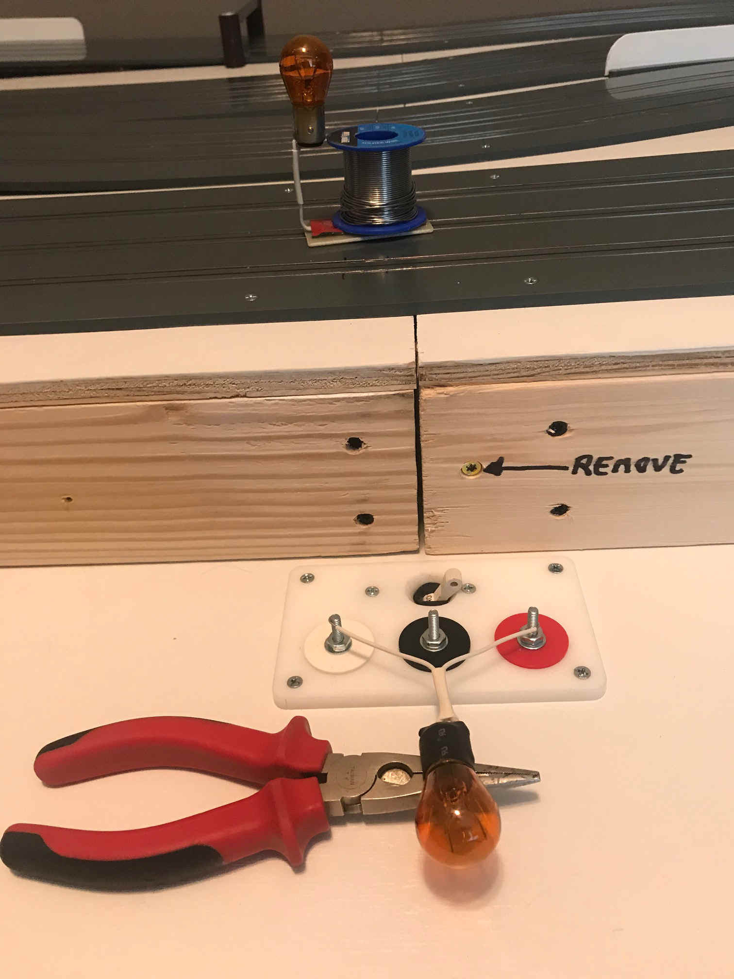
Load Test Fixtures
This second video shows one commercial vendors track wiring including number and location of jumpers. The vendor, Viper Scale Racing, locates one power tap jumper per track section and does not tie adjacent track sectons rails together electrically or mechanically. As such it is not a continuous rail track but a sectional track. I am not singling out this vendor but using their video as it was available. At least one other vendor builds track sections with a single jumper located at the end of the section and does not tie adjacent sections rails together electrically or mechanicallly.
In the above video there are four track sections on a 4 x 16 foot table. Each track section has a single jumper located at one end and the sections are not electrically bonded together. For simplicity let’s say that each track section consists of 16 feet of track. Each sixteen-foot track section contains thirty-two feet of steel rail per lane.
From my work on Magic Raceway I knew that the rail resistance of VSR rail material is 39.77 Ohms/1000 foot at 25 degrees Celsius which is approximately 9.7 times the resistance of #16 AWG copper wire. The rail resistance is dependent on the cross sectional area of the rail and the type of steel used and can vary from vendor to vendor and track to track. It is important to measure the voltage drop of a sample piece of rail and calculate its resistance.
The calculated voltage drop of sixteen feet of track assuming a single jumper at one end and two amp load is 2 amps x 2 rails x 16 feet x 39.77 ohms / 1000 feet = 2.54 Volts or 14.1% of 18VDC. This voltage drop is more than twice the voltage drop in the first video. The problem here is location, loaction and location.
The ideal solution for such a track would be to install two jumpers in each track section. The jumpers would be installed at 25% and 75% of each section. This makes each sixteen foot long section into a an eight foot long center section with two four foot long end sections. For this configuration, the voltage drop for the two four foot long end sections is 2 amps x 2 rails x 4 feet x 39.77 ohms / 1000 feet = 0.64 Volts or 3.6% of 18VDC. Because the center section is fed from both jumpers the voltage drop at the center of this section is the same (0.64 Volts or 3.6% of 18VDC) as calculated above. This simple change reduced the calculated voltage drop by 75%.
It is important to note that the above calculated voltage drops are just for the rail and do not include the voltage drop for under-table wiring, fuses, relays, etc. Depending on how it is done the under track wiring can increase the voltage drop by an additional 1 or 2%.
If you are measuring voltage drop using a light bulb or another load located on the rails it is important to measure the voltage accurately as hundreths of a volt matter. To ensure accuracy, voltage readings were not taken at the light bulb skid but directly from the rails immediately adjacent to the skid. The total load on the power supplies during the test was approximately 5 Amps. The load on the lane being tested was approximately 2.5 Amps. Voltage measurements were taken for each lane at the following points.
Power Supply Panel Output
Drivers Station Input (White to Red Terminal Points)
Drivers Station Output (Black to Red Terminal Points)
Power Taps
Rails at the Midpoint Between Each Set of Power Taps
A ratio was used to correct the test load to match the assumed loads used in the preliminary calculations. The 5 Amp measured voltage drops values were increased by a factor of 6/5 = 1.20 to reflect the diffrence betwwen the measured 5 Amp total and the assumed 6 Amp load. The 2.5 Amp measured voltage drop values were decreased by a factor of 1.0 - (2/2.5) = 0.20 to reflect the change in current from 2.5 Amps to 2 Amps.
The voltage drop across the 12V/18V power supply relay was 0.023 VDC with the relay carrying a 6 Amp load.
The voltage drop from the power supply panel to the drivers station circuit breaker was 0.009 VDC with a total power supply load of two amps per lane or 6 Amps total.
The voltage drop across the drivers station circuit breaker was 0.095 VDC with each breaker carrying a 2 Amp load.
The voltage drop across each drivers station power relay was was 0.006 VDC with each relay carrying a 2 Amp load.
The worst case voltage drop from the drivers station to a power tap was 0.220 VDC with a 2 Amp load.
The worst case voltage drop from a power tap to the track at the midpoint between power taps was 0.290 VDC using a 2 Amp load.
The above measurements show that the worst case total voltage drop from the power supply panel to the track at the midpoint between a set of power taps was 0.643 VDC or 3.57% of 18VDC.
Don't be afraid to question the results. I was surprised at what appeared to be an excessive voltage drop from the drivers station to the power taps. Each table had its own "Ring Bus". Each Ring Bus consisted of two lengths of #14 AWG wire connected together at each end to form a continuous path or ring. The ring bus provided multiple current paths to every power tap. At various points of the ring the power taps branched off the bus. Based on the other values a 0.220 VDC voltage drop didn't look right. I looked at the data and deternined that there must be a single weak link that impacted all lanes equally as the measured power tap voltages were all within 0.008 volts of each other. It turns out that I forgot to measure the voltage drop across the jumper wire that was connected between the driver's station White and Black terminal points. I just included the voltage drop associated with that jumper along with the rest of the Ring Bus voltage drop. The weak link was that "heavy duty" alligator clip jumper which accounted for approximately 90% of the 0.220 VDC voltage drop from the drivers station to the power taps. Since that wire is not part of the track the voltage drop associated with that leg was reduced from 0.220 VDC to 0.022 VDC to remove the voltage drop assocated with the jumper.
The corrected measurements reduced the total voltage drop from power supply to any point on the track from 0.643 VDC to 0.442 VDC or 2.46% of 18 VDC. The revised voltage drop of 2.46% met the 3% design criteria. The need to correct the test results because of a faulty test lead shows how important controller lead wires and alligator clip connections are in determining how much power actually gets from the power supply to the car.
Hopefully I have provided sufficient information to allow you to design your track wiring or to perform a voltage drop test on an existing track. If you are designing a new track, plan the wiring to reduce voltage drop to the absolute minimum.
As a minimum I would recommend #10 AWG, or a #14 AWG for each lane, from the power supplies to the drivers station panel and #14 AWG from the drivers station panel to the power taps. I also recommend that the under table wiring be kept as short as possible while providing multiple current paths to any power tap. Current paths should not be shared between lanes and I would also recommend leaving out, or removing, things you may not need. For example my 4 x 15 foot TKO track has reversing switches installed. My previous 5 x 13 foot MaxTrax layout ran well in reverse and the reversing switches were carried over from it to the TKO. I should have removed the reversing switches after the TKO was tested in reverse and I decided that it would never be raced in that direction. The TKO had a voltage drop of approximately 4.5% from power supply to the midpoint between jumpers. The reversing switches contributed approximately 1% to that value. My 3 x 12 foot Magic Raceway was never going to be run in reverse and, as a result, reversing switches are not installed.
I would also recommend against taking resistance measurements as volt-ohm meters are notoriously inaccurate when measuring low ohm resistance values. This is true of both the older VOMs and today's Digital meters. These meters are very accurate when measuring low voltages and the most accurate way to measure low resistances is to pass a known current through the item, measure the voltage drop and then calculate the resistance (Resistance = Voltage / Current).
Based on my research there is no reason that a continuous rail track should have a total voltage drop from the power supply to any point on the track greater than 4%. This criteria is based on testing of two continuous rail tracks that were wired to minimize voltage drop.
The benefits of testing are learning from the experience and detecting and resolving potential problems. Your track may have a higher voltage drop than expected leading you to add power taps or to make other changes. I took great care to minimize wire lengths and to double up wires when possible to reduce voltage drop. For example, the wires from the power supply panel to the drivers station panel consisted of two #10 AWG wires in parallel. I bought the extra flexible hookup wire about a year before the track was wired. I had extra wire available and threw it in. Doubling up these leads didn't make much of a change but every little bit helps.
I thought about routing #14 AWG wires from my three drivers stations to the power supply but didn't do it as I had the #10 AWG extra flexible wire available. Routing individual positive and negative #14 AWG wires from each drivers station to the power supply would be a good choice for a four or six lane track.
Likewise, I didn't use just mechanical connections but also soldered wires together where possible. A screwed, crimped or twisted connection can still have some resistance or may develop resistance over time depending on the environment. A good mechanical connection that is also properly soldered remains a zero ohm connection forever. Minimize wire length. I used less than 50 feet of #14 AWG wire per lane. This 50 feet includes both the drivers station and the under table wiring. I have seen a 4 x 16 foot four lane track that had over 500 feet of wire under it. The track owner actually bragged about the amount of wire stuffed under the table. I peeked under the table and saw a rats nest of red wire going everywhere with no color coding and no thought given to minimizing wire length! Last but not least, my under table wiring was configured such that there were no shared current paths and multiple parallel current paths to any point. Multiple parallel paths reduce the resistance (and the voltage drop) to any point by approximately 50% and can result in a big gain for a small increase in cost and labor.
Updated March 28 2022