Magic Raceway Construction Update
December 2019 - June 2020
![Rev B[2474]-RED](image001.png)
Since 1975 I have had four home tracks. These are the original Siberia International Raceway (SIR) (1975) which was expanded and rebuilt in 1981 and 1991, Crystal Rock Raceway (2000) and Siberia International Raceway II (2010). SIR II is better known as "The Bear". I thought I was done with track building in 2010 when I took possession of my custom TKO track known as “The Bear”. Unfortunately, with retirement came moving from Illinois to Iowa and my 4’ x 15’ TKO custom routed track had to be sold as it wouldn’t fit in the new space. Fortunately, "The Bear" found a good home at LenJet raceway.
The working title for the new track is “Magic Raceway”. The track will be located in Norwalk, Iowa which is located immediately south of Des Moines. The primary purpose of Magic Raceway is to serve as a practice track and a research and development tool. The track is a three-lane adaptation of Brad Bowman’s iconic Champion Raceway. I fell in love with the original version of Champion Raceway at the first Quad City Quarrel and hopefully this adaptation will work as well as its larger four lane cousin. While the house is large my personal space is not. I have a workroom which is compact but perfect for my needs and a third bedroom which will be my office, computer and track room. The track footprint is reduced from 4’ x 16’ to 3’ x 12’ to fit into the office. Each lane has a lap length of approximately 43 feet. Along with the change to three lanes the design was changed to incorporate variable lane spacing. Like “The Bear” the lane spacing on the main straight in front of the driver’s stations is 2”. The wider lane spacing prevents a driver "thumbing" another car when he is picking up or putting down his own car. Lane spacing gradually changes back to the vendors standard lane spacing in the two large radius curves at each end of the straight. One of the infield turns was also moved slightly to fit in better with an adjacent turn.
Based on my ideas the track was designed by Viper Scale Racing (VSR) in July and August 2019. The track was routed from dark gray Type 1 PVC and was shipped to Iowa in September. In conjunction with routing, preliminary plans were made for the table, crash walls, the elevated section and wiring. Over the winter the infrared sensors will be developed and tested.
In the spring table construction will begin. The table will use 2” x 4” construction with a 1/2” plywood surface. The elevated section will be supported with 1/4” plywood. Table legs will be similar to those used on “The Bear” and “Crystal Rock Raceway”. The table and leg structure will be fully triangulated and the table will be rigid. Once the table is built the elevated sections will be constructed. Once this is done the track will be mocked up and holes drilled for mounting screws, power taps and infrared sensors. The track will then be removed and the table will be sanded and finished. Finally the track will be secured to the table and wired. The light bridge will be built, circuit breakers, relays and drivers stations installed. Finally the track will be interfaced with the Slottrak Race Management System (RMS). Slottrak is the official timing and scoring solution of HOPRA.
Wiring
Power wiring will use the double fed ring bus design first used on “The Bear”. Location of the power taps and the #14 AWG power wiring are shown below. Each table half will have its own Ring Bus. Each bus will be fed from a central table terminal block. A jumper will connect this terminal block to a terminal block located on the driver’s station panel. The Ring Bus design reduces resistance to any point on the table as two #14 AWG wires connected in parallel have a resistance equivalent to an #11 AWG wire. The design also ensures multiple current paths to any point on the table. To further reduce voltage drop each lane will have its own dedicated positive and negative wires and current paths will not be shared between lanes downstream of the drivers station. The design was revised to add a jumper directly from the drivers station directly to the opposite end of the table and to better clarify which jumpers are removable. The solid lines show permanent wiring which will be #14 AWG solid copper wire. The dashed lines show removable jumpers which connect removable table sections. These jumpers will be made from #14 AWG stranded copper wire. The revised design essentially duplicates the proven ring bus design installed on "The Bear". To minimize voltage drop the positive power supply lead will be terminated at the driver's station panel as the circuit breakers and relays are located there. For the same reason the negative power supply lead will be terminated at the primary table terminal block. Jumpers will be routed from this terminal block to the driver's station panel and power taps located on each table section.

Magic Raceway Single Line Showing Power Taps and Track Wiring
Each lane will have a 40 Amp rated power relay allowing for individual lane control. Like my two previous tracks each lane will be protected by a 5-Amp Airpax model 52-502-91 DC rated thermal/magnetic circuit breaker. The breakers are identical to the ones used on CRR and “The Bear”. I have a twenty-year operating history with these breakers. These new old stock breakers are designed to protect the power supply, track wiring, relays and the track rails. They are not designed to protect an improperly wired controller. Wiring from the power supply to the driver’s station terminal block will be #10 AWG. The Airpax breakers are designed for a maximum voltage of 65 VDC which exceeds the maximum track voltage of 20 VDC. The breakers are new old stock and are in excellent condition. Historically, breakers stored in a clean environment do not degrade and breaker performance is assumed to be equivalent to a new breaker. Each breaker is designed to trip at a current equal to or above 6.25 amps. The breaker’s time-current trip curve is shown below. The upper and lower lines represent the minimum and maximum breaker response times. The curve shows that the breaker will not operate until the fault exceeds 125% of the breakers rating. For a 20A fault (400% of 5 Amps), and the continuous output rating of the power supplies, the breaker will trip between 0.15 and 2 seconds. For a 25A fault (500% of 5 Amps,) and the power supplies maximum short term output, the breaker will trip between 0.013 and 1.3 seconds. These trip times will adequately protect the track and the track wiring. As stated previously, the breakers are not designed to protect a miswired controller. Because of the various types of controllers and components located within controllers it is impossible for one type of overcurrent device to adequately protect all controllers. To adequately protect each controller overcurrent protection should be built into the controller.

5 Amp Circuit Breaker Time-Current Curve
The manufacturer's data sheet indicates that each breaker has an internal DC resistance of 0.0590 Ohms. Assuming a two-amp per lane running current, each breaker would have a voltage drop of 0.118 Volts or 0.66% of 18 Volts. A typical slot car when running is a load of less than one-amp. For purposes of design I am assuming a two-amp load per lane. A two-amp load is approximately 33% of the breakers trip current and spurious trips are not deemed credible. This assumption has been validated by experience with CRR and "The Bear" which used the same circuit breakers.
The wiring from the power supply to each relay is #10 AWG copper wire. The wiring from the relays to the track jumpers is #14 AWG copper wire. Short leads from the track to each Power Tap terminal block will be #16 AWG copper wire having a maximum length of 12 inches. Because of the way the power taps are configured each connection will consist of two #16 AWG wires routed in parallel. Two #16 AWG wires connected in parallel have a resistance slightly lower than that of #14 AWG wire. However, the jumpers are assumed to be #14 AWG wire. Per the NEC #14 AWG wire has a resistance of 2.575 Ohms per 1000 feet @ 25C/77F. Each lane will have dedicated positive and negative wires and downstream of the drivers’ station current paths will not be shared between lanes.

Airpax DC Thermal Magnetic Circuit Breaker
Conservative calculations indicate that the worst-case voltage drop to any power tap on the table will be approximately 1.5% assuming a two-amp per lane load at a power supply voltage of 18V. The calculation resistances include #14 AWG wire at 0.0026 ohms/ft., 0.0150 ohms for each lane's power relay and 0.0590 ohms for each lane's circuit breaker. A 1.5% voltage drop equates to a voltage of 0.28V assuming a two amp per lane load and a power supply voltage of 18V. The calculations use very conservative wire lengths and may be redone using actual lengths once the track is built. The calculations will be verified by a load test similar to the one performed in the following video.
https://www.youtube.com/watch?v=qsNIDHvUoUk
This YouTube video made by "Tossedman" shows the results of a HO track load test including voltage drop from the drivers’ station, to a power tap and to the midpoint between power taps. It should be noted that this was a routed, continuous rail track. The voltage drop to the midpoint between jumpers would have been more severe if it would have been a sectional track because of the contact resistance of the individual track sections.
In the video the load was a light bulb which provided a 2.5-amp load for the power supply and track wiring. The result of the test showed a 0.5 volt drop between the driver’s station and the power tap. The voltage drop between power supply and power tap at Magic Raceway would be 0.28V. In the video the total voltage drop between the power tap and the track at the midpoint between power taps was an additional 0.73 volts. The total voltage drop was 1.23 volts or 6.8% of 18 volts and the voltage at the midpoint between power taps was 16.77 volts. It should be noted that the voltage drop between the power supply and drivers’ station was not measured. From the video the power supply appears to be set at 18.1 volts. If this is so then the total voltage drop from the power supply to the load would be 1.33 volts or 7.3% of 18.1 volts. To allow for a comparison with my calculations, which use a 2 Amp load, and the video I used a ratio to correct the voltage drop for a 2 Amp load. If the load in the video was reduced to 2 Amps, then the total voltage drop would be reduced from 7.3% to 5.84%. In my opinion a 5.8% voltage drop is excessive and not acceptable.
The initial test used a three-amp fuse at the driver’s station. A three-amp fuse is good for all HO cars except for highly modified cars with neo magnets and rewound motors such as CMPM, drop-in neo or unlimited. For these I would use a six amp fuse. The test was then repeated with a 30-amp fuse. This reduced the total voltage drop by 0.2 volts. The 30-amp fuse load test was done just to show the impact of the fuse resistance on voltage drop. A 30-amp fuse is inappropriate for a HO slot car track as the fuse would not have protected the car, track, track wiring, controller or the power supply. It would have been nice to see the results with a six amp fuse. The BUSSMAN website shows that the internal resistance of 3, 6 and 30 Amp AGC fuses are 0.045, 0.020 and 0.002 Ohms respectively. Replacing the 3 Amp fuse with a 6 Amp fuse would have increased voltage at the power tap by approximately 0.1 volt. This is a worthwhile improvement with no real downside. The fuse substitution would have also reduced the total voltage drop to 1.23 volts which is 6.8% of 18.1 volts. The video had no conclusions or recommendations. Personally, I would consider upgrading the track shown in the video to add more power taps along with upgrading the wiring between the drivers stations and track to attempt to reduce the total voltage drop to 3% or less.
Magic Raceway will have power taps located a maximum of eight feet apart. Six #14 AWG wires (two for each lane) will be run to each power tap. Each power tap will consist of two lengths of #16 AWG wire routed in parallel. The #16 AWG jumper resistance is equivalent to the same length of #14 AWG wire. As described above the wiring for each lane will be a double ended ring bus as this offers multiple current paths and thus less resistance from the power supply to any point on the track. The VSR rail dimensions are 0.020" x 0.100" which gives the rail a cross sectional area equivalent to #16 AWG wire. Per the NEC #16 AWG copper wire has a resistance of 4.094 Ohms per 1000 feet @ 25C/77F. The resistance of steel is between 3 and 15 times that of copper. Assuming that the VSR steel rails have a resistance equal to ten times that of #16 AWG copper wire (i.e. 40 Ohms/1000 ft), the expected voltage drop for the four feet of track from a power tap to the midpoint between power taps would be 0.64 Volts assuming a 2 Amp load. The total expected voltage drop from the power supply to the midpoint between power taps at Magic Raceway would be 0.28 volts + 0.64 volts = 0.92 volts. This equates to a total voltage drop of just over 5% of 18VDC. It should be noted that these calculations do not take credit for parallel current paths to any point on the track provided by the ring bus wiring arrangement. Crediting these parallel paths will reduce the calculated voltage drop to 3%. The final "as built" calculations will credit these parallel paths and will be verified by test.
The individual lane power relays arrived January 28. They are model JD2912-1Z-12VDC relays sourced from Amazon.com. The major difference between these relays and the 40A relays mentioned earlier is that these relays have a contact rating of 80A @ 14VDC as opposed to 40A @ 14VDC. The relay coil current draw is identical to the originally proposed 40A relays. The new relays physical footprint is slightly larger than the 40A relays. There is plenty of space at the drivers panel for the new relays and the larger footprint is not a concern. The new relays contact voltage drop as measured by test is 7 mV with a 2.44 Amp load. This measured value translates to a resistance of approximately 0.003 Ohms which is considerably less than the 0.015 Ohm contact resistance value of the originally proposed 40A relays. The relays lower contact resistance will further reduce the total voltage drop. The 80A rated relays were a lower cost option and appear to be a worthwhile investment.
Track Automation and Lapcounting
The track will use Slottrak for lap counting and lane power control. The Slottrak Race Management System (RMS) functions as a lap counter and lap timer. It will operate on tracks from 1 to 8 lanes. In addition to simple counting and timing, Slottrak will run various types of races complete with lane rotations and optional individual lane power control. The timing resolution is 1 millisecond. Results are saved, and can be recalled for viewing and race report generation. The RMS will runs on all versions of Windows from Windows 2000 up to and including Windows 10. The parallel, serial, joystick port and the TrakMate Windows (TMW) hardware may be used for lane input. SlotTrak is also compatible with other interface systems. The parallel port, serial port, or TMW hardware may be used for track calls. The parallel port, serial port, TMW hardware (track power) or phidget cards (individual lane or track power) may be used for power control. Slottrak is also the only RMS authorized by HOPRA for use at their National Championship races
Magic Raceways Slottrak race management lap counting system and lane power control will use a 0/16/16 Phidget digital Input/Output card and a Windows 10 Lenovo I-5 computer. The 0/16/16 Phidget card is supported by Slottrak however, to my knowledge this is the first time that this card has been configured to work with infrared sensors, provide individual lane power control and support other features such as track call pushbuttons and indicating lights. The cards ability to control individual lane power relays is documented on the Slottrak website. A variation using this card and infrared sensors was developed in early 2019 to inform Slottrak when a car was in the pits. Preliminary tests show that the software will accept lap counter inputs and track call inputs from the 0/16/16 card. The design will be fleshed out over the winter. There may be problems but I am confident that the final design will be successful. The Phidget card is also a low cost solution to the problem of how to count laps and control lane power. A 0/16/16 card can be obtained for less than $100. The similar 8/8/8 card can be obtained for less than $80. Slottrak is one of the premier Race Management Systems (RMS) available and is currently donation-ware. The combination of a Phidget card and the Slottrak RMS is expected to offer a cost savings over so called "plug and play" systems such as Viasue and Trakmate.

0/16/16 Phidget Card
The 0/16/16 Phidget card will be used to individually control lane power and inform the race management system when a car crosses the lap counter. Phidget digital outputs 0, 1 and 2 will be used for lane power control. Digital output 3 will remain spare. Digital Outputs 4 through 8 will be used for race status LEDs and time remaining LEDs. The remaining outputs are currently unassigned.
Phidget digital Inputs 0, 1 and 2 will be used for infrared sensor inputs. Digital input 3 will remain spare. Digital input 4 will be used for the Track call pushbutton input (if installed). The remaining inputs are currently unassigned.
The coils of the 80 Amp rated 12V automotive relays that I will be using to switch track power draw 0.15 Amps each when energized with 12 VDC. This is well within the cards 2 Amp digital output current rating. The total draw when all relays are energized will be 0.45 Amps. Therefore, the 12 VDC filtered and regulated power supply will have a minimum output of 1 Amp. The power supply will be backed by 10,000uf (minimum) capacitator bank to allow it to accommodate surge currents such as when the three track power relays simultaneously pull in.
As the relays are an inductive load each Digital Output will be protected with a reverse biased diode connected across the relay coil to prevent an inductive kickback voltage spike from damaging the Digital Output. The relay is an inductor and a negative voltage spike will occur when power is removed from the relay. The magnitude of the voltage spike depends on the inductance of the relay coil, the current flowing through the relay coil and the time required for the current to reduce to zero. For a relay coil deenergized by opening a switch the voltage is limited by the spark across the switch contacts when it is opened. Assuming that the air gap between the contacts is 1mm the open circuit voltage spike will be -3000V or 250 times the 12 VDC initially applied to the relay coil. The addition of a reversed biased diode wired across the relay coil provides a current path for the voltage spike and reduces its magnitude to the forward voltage of the diode which is approximately 1 VDC. A very good tutorial on inductive kickback, the theoretical and real world magnitude of the kickback and how the addition of a diode (or a resistor in series with a diode) can minimize inductive kickback can be found here.
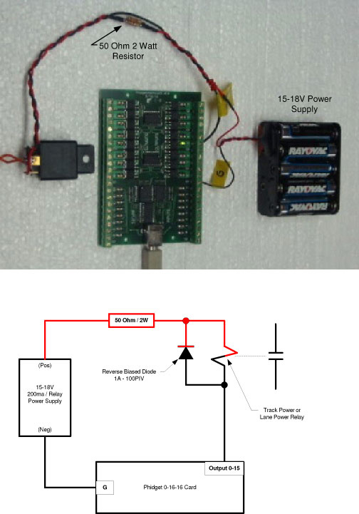
This diagram taken from Slottrak's web site shows the wiring of a typical Phidget Output and the reversed biased diode
The above photo shows a 50 Ohm relay connected in series with the relay coil. As Magic Raceway will use a 12VDC auxiliary power supply the dropping resistor is not required. In the photo the diode is connected at the relay coil terminals and cannot be seen. The light bridge, lap counter sensors and track call digital inputs will also use the 12VDC supply. The lap counter sensors are the subject of a research project. An update on the status of the project is provided as part of this page.
Personally I find that having the PC display in view during a race is distracting. Glancing up from the track to view lap times or the gap between you and others can lead to lost time or crashes. As a result the screen will be located away from the track at the race directors position. The RMS, via the Phidget card's digital outputs, will provide information to the drivers via a “Christmas Tree” built into the side of the light bridge facing the drivers. The light bridge is located on the back straight and at the approximate table centerline. This position makes it visible to all drivers. The tree will consist of four yellow LEDs, two red LEDs and two green LEDs. The LEDs are 3mm in diameter and are water clear. The tentative LED arrangement is as follows. I am also open to an inverted version of the following.

Light Bridge "Christmas Tree" Warning Lights
The Christmas Tree will provide the following information to the drivers:
Start Light Sequence: The four yellow LEDs will illuminate from bottom to top mimicking the Slottrak on screen "Christmas Tree". Just before the race starts all four yellow LEDs will be lit. When the race starts the red and yellow LEDs will go out, the green LEDs will go on and power will be applied to the track. This start light sequence applies for both segment starts and for restarts following a track call.
End of Segment/Race: The bottom yellow LED will illuminate with 20 seconds left in the segment or race. The remaining LEDs will come on at five second intervals progressing from bottom to top. With five seconds left in the segment or race all four yellow LEDs will be lit. When the race is over power is removed from the track, the yellow and green LEDs will go out and the red LEDs will be lit. If the "Race to the Line" option is selected then power not be removed when time has expired. Power will be removed to each lane as its car crosses the lap counter after time has expired.
End of Lane Change Period: The bottom yellow LED will light with 20 seconds left in the lane change period. The remaining yellow LEDs will come on at five second intervals. With five seconds left in the period ends all four yellow LEDs will be lit. When the lane change period ends the yellow LEDs will go out and the Start Light Sequence will begin
As per usual practice, sounds will be used to indicate when cars cross the lap counter, there is a fast-lap, time remaining in both the segment and in the lane change period along with the start sequence beeps and other audible notifications. Slottrak can provide audible lap time information. Personally, I find computer voiced audible lap times distracting and this feature will not be enabled.
The following is the second draft of the schematic diagram for the 12 VDC control circuit that will allow the Phidget card to control individual lane power, LEDs and interface the infrared detectors with the Phidget card. This revision made the positive bus wires RED and corrected the wiring associated with the Aux Relay. This diagram does not include the light bridge or track main power. The light bridge will be powered from the same 12 VDC supply that powers this control circuit. The light bridge design will be a three lane version of the one discussed in this Tech Pages article. Like the Tech Pages article the bridge will have two independent infrared LEDs for each lane. The sensors will be set such that one LED will provide sufficient infrared light to bias the sensor OFF.
The gray rectangles labeled "R" in the following diagram are voltage dropping resistors. The final value of each resistor will be determined after the LEDs are sourced. Each relay has a reversed biased diode connected across its coil terminals. The function of these diodes is to protect the circuit components from voltage spikes that occur when each relay is deenergized. If not controlled, these voltage spikes could damage the LEDs, Phidget Card or the Infrared Detector Modules. All control power wiring will be #22 AWG stranded copper.

Preliminary Control Circuit Schematic Diagram
The following is the first draft of the schematic diagram for main track power. The 12 V and 5 V track power supplies are rated for 20 Amps continuous output and will provide track voltage at any value between 10 and 20 VDC. As can be seen the 12 VDC Control Power Supply will feed the Relays, LEDs, Sensor and the Light Bridge. Main power wiring from the power supplies to the circuit breakers is #10 AWG. Based on the planned location of power supplies, breakers, relays and drivers stations it is unlikely that more than 10 feet of #10 AWG wire will be installed. The remaining power wiring is #14 AWG. Each lane has a dedicated power and return wire and current paths are not shared between #14 AWG wires. A short length of double #16 AWG wire will be run from the track power tap to a terminal block located adjacent to the power tap. Control wiring will be #20 AWG. With the exception of #16 AWG wire all wiring is stranded copper. The #16 AWG wire will be tinned solid copper.

Preliminary Track Power Schematic Diagram
Not shown in the above diagram is an output filtering capacitator. As both main power supplies are switching type supplies an active filter will improve power quality. If installed, the output filtering capacitator will use a 10,000 ufd capacitator installed in a capacitator multiplier circuit. This circuit uses a transistor to multiply the capacitor's value by the gain of the transistor. Assuming that the transistor has a gain of 100 then the equivalent value of the capacitator would be 10,000 ufd x 100 = 1,000,000 ufd or One Farad. Darlington pair transistor's have gains that exceed 1,000. Using a transistor with a gain of 1,000 would increase the equivalent value of the capacitator to 10 Farads. The purpose of the capacitator is not to provide surge current but to provide filtering. A large capacitator will provide filtering and surge current but can also damage the power supply in the event of a short if the capacitator not properly isolated from the power supply.
Construction
Construction began with unpacking the box and inventorying the contents. VSR fills the box with Styrofoam peanuts. If you take your time it is possible to unpack the box without peanuts going everywhere. The track arrived undamaged and with all required parts. Each track section was separately wrapped in plastic. The ends of each track section were protected with removable plastic half dog bones. In my opinion, the packing was excellent and the track was well protected. After unpacking, I modified one section of track to allow the lap counter’s phototransistors to be installed. The track was then mocked up and the red lane identified on each track section. Then, it was time to install rail and lock wire.
Installing rail was a concern as I have NEVER installed rails or railed a track of any kind. VSR offers a kit with their rail installation tool and a short piece of three lane track to allow you to develop your rail installing skills. Might be a good investment but I did not go that route and started cold turkey.
The VSR rail installation videos were very helpful and installation was straightforward once I learned how. The video shows one way of using the installation tool. You have to develop your own process if that way doesn’t work for you. I am assuming that the track section used in the video was Sintra. Sintra is an expanded PVC foam and Sintra is soft compared to Type 1 PVC. From working on my TKO and Maxtrak tracks I learned that Sintra will distort or flow when the pins or power taps were pressed in making installation easier. The same would be true when the lock wire is installed.
As both the Maxtrax and "The Bear" suffered slight damage from guide pin impacts and crashes my VSR track was routed using Type 1 PVC which is a solid, rigid material. The corners of the slots are hard and sharp. A hard sharp edge is great for the guide pin slot and rail side of the two power rail slots. It’s not good for the lock wire side of the slot as the sharp edge tends to catch the lock wire and damage it making installation difficult. This can be seen in VSRs rail installation video. To prevent this damage I found that additional steps are required when railing a Type 1 PVC track.
Breaking (or rounding) the edge of the lock wire side of the rail slot allows the lock wire to slip into the slot without damage. Fortunately, I have a few small triangle shaped tungsten carbide cutting bits for use with my Unimat lathe. One or two light passes with the cutting bits broke the lock wire edge of the rail slot and the rail and lock wire were ready to be installed.
The rail and lock wire were installed using the VSR rail installation tool using a multi-step process. The VSR tool consists of two large bearings, a washer and a half-inch diameter steel rod. The rod is undersized compared to the inside diameter of the bearing and the washer. This allows the bearings and washer to rock and roll with respect to the rod. At first this seemed unusual. As I used the tool, I found that the loose fit was a benefit. I installed a collet onto one end of the rod to provide a thrust plate for bearing to push against when side loads were placed on it. The collet works much better than having the bearing press against your bare hand.

Modified VSR Rail Installation Tool
The first step cuts the rail and positions it in the slot using weights or tape to keep the rail in the slot. The rail is not precisely cut to length but is cut so that approximately half an inch extends from each end of the track section. After the rail is cut the sides of the rail are sanded using an 80 grit cloth and then the rail is wiped down with acetone or denatured alcohol to remove all oil and dirt. Removal of all oil and dirt is critical to a good installation.
The second step uses the tool with the washer centered between the two bearings. The washer is placed in the guide pin slot and the bearings bottom the rail into the slot and sets the lock wire flush with the top of the rail. In the installation video the tool is pushed away from the installer. I found it easier to draw the tool toward me. In this step the rail and wire are routed into the slot and pushed into place by one of the two bearings. This worked well in the straights and in long radius turns. In the short radius hairpin turns the washer could bind and I found that it was better to remove the washer and use only the bearings to push the rail and lock wire into the slot.
The third step used a single bearing to push the lock wire flush with the top of the track surface. In this step the rod and bearing are held at an angle so that the side of the bearing rests on the lock wire side of the rail. In this step the rail acts as a guide and keeps the rolled edge of the bearing resting on the lock wire. This step sets the lock wire flush with or slightly below the PVC track surface. This step may not be necessary with Sintra but I found it mandatory with the rigid Type 1 PVC.
The fourth step used a single bearing and the washer to seat the lock wire in its final position beneath the surface of the track. In the hairpin turns the washer was used without the bearing to seat the lock wire.
Finally, both bearings and the rod were used as a rolling press to ensure the rails are fully bottomed into their slot. The washer was used with a bearing or by itself to address places where the lockwire was not fully bottomed.
Some force was needed to install the lock wire and appropriate care should be taken when railing a track routed from the softer Sintra material. My installation left a few scratch marks on the harder Type 1 solid PVC material. These scratches were made when the edge breaking tool slipped and skidded from one rail slot to another. The scratches are not significant and for the most part buffed out. As the edge breaking step is not required with a Sintra track I am sure that a modified version of the above process would work well on a Sintra track.
Work Planning
I planned my work and worked my way in from the straights and to the tighter turns and hairpins. The first day I railed the three straight track sections. This day was the most frustrating as I hadn’t figured out that I needed to break the edge before installing the lock wire. As a result sections of lock wire were damaged during installation. Overnight I discussed the lock wire issue with VSR's Dan who suggested breaking the edge of the slot before installing the lock wire. Things went much easier after I incorporated that step. The large radius infield “S” curves were the subject of the day two. This is when I developed and added the step to use a bearing set at an angle to seat the lock wire flush with the top of the track. The step only moves the lock wire a maximum of 0.015” but made the final step that much easier. The track sections containing the two large radius 180 degree turns and the four hairpin turns were planned for days three and four. I really got the hang of it on day two. Once I perfected the steps and put the process together, I managed to complete the rail and lock wire installation in three short, days. Starting over, I am confident I could complete the track in two short, easy days.
Once the rails were installed, I trimmed the ends of the rail flush with the ends of each track section and finish cut the lock wire at the power taps and at the ends of each track section. In the spring I will go over the rails and lock wire one last time and glue the rails and lock wire into position before installing the track onto the table.
The rail and lock wire will be bonded to the PVC using a water thin superglue. The superglue can be used to bond the rail in spots or over the entire track. Bonding the entire track is recommended if you plan on running drop in NEO or Unlimited cars. I don't plan on running these cars but I am considering doing the entire track as opposed to just spot gluing the rails. The rail and track will be wiped down with acetone and allowed to dry immediately before the glue is applied providing a clean, oil free surface for the Cyanoacrylate adhesive to do it’s magic. If necessary, the rails will be honed to a consistent 0.011” height once they are glued into place.
Power Taps and Track Joints
I wasn’t excited by the VSR power tap design and decided to use a variation of the TKO power tap design. The VSR power tap design does not tie adjacent track sections together electrically. Each track section is powered by its own power tap. My variation of the TKO design powers each track section from both ends and adjacent track section rails are tied together mechanically and electrically. This provides more current paths to the car and reduces the voltage drop caused by the steel rails. The TKO system installs spring pins in the lockwire slots between adjacent track sections. The pins align and tie adjacent track sections together mechanically and electrically. The spring pin installation also provide multiple current paths to the car. The following photo is a mockup of one of my power tap installations. As seen in the photo the lock wire was not installed in the last half inch of each track section. Holes were drilled in each rail slot at the end of the lock wire. Number 16 AWG tinned solid wire is formed into a "U" shape and is installed in the gap between the lock wires to align and tie the adjacent track sections together. The #16 AWG wire is the same diameter as the lock wire and is an interference fit assuring good electrical contact with the rail. Both ends of the wire will be passed through the holes drilled in the track and table. The wires will be twisted together beneath the table to secure the track to the table and to align and lock the track sections together. This installation method eliminates the need for the "Dogbones". Finally. this method allows the power tap wires to have the a slightly lower resistance per foot than the #14 AWG under table wiring, The rail installation tool will be used to seat the power tap wire beneath the track surface. The diameter of the 16 AWG wire is 0.0508". I used a 1/16" (0.0625") drill bit. Once the track is mocked up on the table the 1/16" holes will be used to drill pilot holes through the table top. The track will then be removed and the pilot holes will be enlarged to a minimum of 3/16".
At each power tap location the two #16 AWG wires will pass through the table top and terminated at a terminal strip located under the table onto which the #14 AWG ring bus wires will also be terminated. Prior to termination the power tap wires will be twisted together underneath the table top to secure the track to the table. This method aligns the track sections together, provides each track section with multiple power taps and bonds the rails from adjacent track sections together. It also minimizes the need for fasteners to secure the track to the table, makes the dogbones redundant and eliminates the large holes in the track associated with the VSR power tap design. Eliminating grooves and holes adjacent to the rails was a lesson learned from my Maxtrax. With the Maxtrax several T-jet guide pins were sheared off when they dropped into the track section joint potholes at speed. This wasn't a significant issue with the TKO as the number of track joints and the associated potholes was significantly reduced. One goal of the Magic Raceway design is to entirely eliminate these potholes!

Partially Mocked Up Power Tap
This method of installing power taps worked very well with my TKO and should work equally well here. The TKO installation did not use tinned wire and did not solder the wires to the rails but coated both the wire and the rails with SANCHEM Incorporated NO-OX-ID "A-SPECIAL Electrical Grade" grease prior to installation. This grease is designed to prevent the formation of oxides, sulfides and other corrosion deposits on copper, aluminum, and steel surfaces and is legendary for preventing the corrosion or oxidization of electrical connections. The TKO was made from Sintra which is more susceptible to heat damage which is another reason that the power taps were not soldered to the rails. Type 1 solid PVC is more heat resistant and testing has shown that, if necessary, the tinned #16 AWG power tap wires can be soldered to the rails without damage.
While the power taps secure the track to the table surface they are not the only means used to secure the track to the table. Holes will be drilled along the track outer edges and #6 flat head wood screws will be installed to secure the track to the table surface. With the exception of the four track joints that bridge the split between table sections the dogbones will be glued in place.
To allow the table to be easily split into two sections for transport, this method is not used for the four track joints that bridge the split between the two table sections but are only used for the track joints that are located away from the table split. I haven’t quite figured the table split installation out but I have made track joints work successfully at table splits with my three previous tracks and will succeed here too. I am considering using non corroding 1.5mm stainless steel expansion pins at each table joint to align and tie the rails together in a manner similar to the method used on the TKO. The diameter of the 16 AWG wire is 0.0508". The uncompressed diameter of the pins is 0.0591" and they should work well in this application. The pins will be coated with SANCHEM Incorporated NO-OX-ID "A-SPECIAL Electrical Grade" grease prior to installation. I coated the pins on my Maxtrax during its rebuild to repair damage from using water based cleaners and to add two additional power taps. When sold and taken apart several years later for its move to Ohio no corrosion was observed on either the pins or the rails. I coated the pins on my TKO when the track was first built and 10 years later when the track was disassembled for its move to the East coast the pins and rails were in prefect condition. This stuff works! Once I have the final solution the “Dogbones” at these four track joints will most probably be cut in half and glued to their respective track sections. Its highly unlikely that the dog bones will be used to align and tie the track together at the table split. Hindsight is 20/20 and if I had to do it over again I would have left the dog bones out of the original design.
Track Power Supply
A Rivergate “Bulldog”, 20 Amp, 12 VDC power supply wired in series with a MeanWell RSP-100-5, 20 Amp, 5 VDC power supply will provide track power. Both power supplies are fully regulated and have overcurrent protection. This combination allows easy switching between 12V and 18V. A 20 Amp supply can continuously provide 6.7 Amps per lane and a surge capacitor is not required. A 20 Amp relay will switch the 5 V supply into the track power supply circuit when 18 V is required.
The 12 V power supply voltage can be adjusted, however the normal adjustment point is extremely hard to reach. Therefore, the Bulldog power supply was modified to add external voltage control to allow its voltage to be easily adjusted over a range of 10 to 18.6 VDC. Utilizing the full Bulldog voltage range allows the track voltage to be a maximum of 23.6 VDC. There will never be a race on this track with that voltage! In addition, components internal to the Bulldog got uncomfortably warm when its voltage was turned up to maximum. I didn't want to risk damage to the power supply therefore the Bulldog will be limited to a maximum of 15V. With the addition of the second power supply track voltage can be comfortably adjusted over a range from 10 to 20VDC.
The control box shown in the following photo will monitor track voltage and allow adjustment of the Bulldog 12V power supply. From top to bottom the remote box has the following controls and indications; Power ON LED, Voltmeter ON/OFF pushbutton switch, 5-30 VDC Voltmeter, 10-Turn Voltage Control Rheostat. Normally the voltmeter will be turned off. The voltmeter measures track voltage and will be turned on only to verify and adjust voltage. The red Power LED is also connected to track voltage and indicates when the power supplies are ON and operating.

Power Supply Remote Panel
The following figures show the 120 VAC and low voltage power supply wiring. The line voltage wiring will be routed and installed in rated enclosures to protect against accidental contact. Low voltage wiring will be left exposed. As shown in the first figure a three position (ON-OFF-ON) double pole double throw switch will provide 120 VAC to the Power Supplies and the Power Supply Relay. This switch is mounted remote from the Power Supply Remote Panel shown above. When the switch is in the Down position only the 12 V supply will be active and the relay contacts will disconnect and bypass the 5 V supply. When the switch is in the Up position the 5 V supply will be turned on and the relay will be energized to connect the two power supplies in series. Placing the switch in the center OFF position removes power from both power supplies and the relay. The track power supplies will only provide track power. A separate Auxiliary 12 V Power Supply will provide power to relays, light bridge, LEDs and other accessories.

120VAC Wiring
AC wiring terminations are located behind protective barriers. A removable panel covers the power supply area. The panel has horizontal extensions on the top and bottom that allows cooling air but denies access to inquisitive fingers.
The second figure shows how the Power Supply Relay (RELAY) will switch the 5 V power supply into and out of the power supply circuit. The relay contacts are rated for a minimum of 20 Amps DC and can safely carry the power supplies maximum output. There is no concern about shorting the 5 V supply as when the power supply is powered down the normally open contact will first open to isolate the power supply before the normally closed contact closes to bypass it. When the 5V supply is powered up the normally closed contact will open to remove the bypass before the normally open contact closes to connect the 5 V power supply in series with the 12 V supply. The diagrams show an AC relay being used. The 5 V power supply may be shorted when its power is removed as an AC relay operates quickly when power is removed. When push comes to shove I may use a DC relay for this application as I believe I have a 40 Amp rated Potter and Brumfield relay on hand whose coil operates on 12 VDC. If that is the case there will be a small DC power supply added to the circuit to provide DC voltage for the coil. The addition of a capacitator to the power supply output will delay the relay dropping out by a few tenths of a second when AC power is removed. This short time delay will allow the power supply to safely shut down before it is bypassed.

Low Voltage Power Supply Wiring
Table Joint
The table will consist of two 3' x 6' sections. The center joint will be a bolted connection that is designed to allow the table to come together precisely in all three dimensions. This should eliminate the need for keys or dog bones at the table split. At least that was the case with my first track. When it was time to move Siberia International Raceway for the last time the track sections were cut at the table split using a razor saw. When reassembled, the table track joints were aligned and silent. The Maxtrax was sold minus table and some of that table was recycled to form "The Bear's" table and drivers stations. "The Bear" had expansion pins that tied the track together at the table splits. I did turn some laps with the pins removed and the joints were silent. "The Bear" also went together without issue after its move from Illinois to LenJet Speedway. Based on these experiences I am expecting good results with Magic Raceway's table joints.
The following figure shows a top and side view of the table joint which is the same style joint used on CRR and "The Bear". The 2" x 4" frame and the plywood top form a pocket into which the adjacent track section is inserted into. The bolts then tie the whole thing together into a solid piece. What the figure does not show is the screws that go from the track section into the adjacent table top. That, plus the indexing table joint, is what aligns the track in all three dimensions. Diagonal bracing is added between the legs and the table to "box" the table add stiffness in the X, Y and Z dimensions. When done, I was able to pick up one end of "The Bear's" table while the diagonally braced, three piece tabletop remained razor straight. The same will be true with Magic Raceway's two piece table. For transport a dummy 4" x 4" is bolted to the recessed 2" x 4". The dummy 4" x 4" extends past the exposed track section hopefully protecting it from damage. I used 4" x 4" dummy blocks to protect the overhangs when transporting "The Bear" from Illinois to Len Jet Raceway. They worked perfectly and the track made the pothole filled 1,000 mile trip without damage.

Table Joint Detais
Race Management System Interface Card Experiments
The Slottrak RMS can be used with a number of Input/Output cards. My last track used a Trackmate card for the lap counter sensors and track call pushbuttons. Individual lane power control was provided by a separate 0/0/4 Phidget relay card. With my new track the goal is to do everything with one 0/16/16 Phidget card. The card's 16 Digital Inputs will accept lap counter optical sensors and track call pushbuttons (if installed). The cards 16 Digital Outputs will control the individual lane power relays, LEDs and other accessories. The goal is to wire the photo transistors directly into the card’s Digital Inputs. I also wanted a reliable over the counter detection system. I was looking at options and discovered these Infrared flame detectors. They are available from both E-Bay and Amazon in response to a search for “Infrared Flame Detector”. The detectors are inexpensive and their infrared operating range encompasses the 850 nanometer wavelength normally transmitted by infrared light bridge LEDs. The detectors operate on 12VDC and provide isolated relay contact outputs. A plus is that the detectors sensitivity can be adjusted to fit the installation.

Infrared Flame Detector With Relay Output
The wiring for the above relay output type infrared flame detector is simple and is shown in the following figure. A single 12 VDC regulated and filtered power supply powers the Digital Input and the Infrared Flame Detector card. The positive power supply terminal is connected to the VCC pin on the detector card and to the relays common contact. The negative power supply terminal is connected to the GND pin on the detector card and the Phidget card ground (G). The normally closed contact of the relay is wired to Phidget card Digital Input. In this case the relay was wired to Digital input 0. Each detector has a green and red LED. The red LED illuminates when the detector is on. The green LED is on when the optical detector does not see any Infrared light (i.e. Fire). The relay is picked up (green LED off) when the detector sees infrared light (i.e. Fire) above the sensitivity threshold. I wired the detector such that contacts close when the relay drops out and the green LED is on. This contact arrangement applies a voltage to the Phidget card digital input when a car breaks the light beam. Based on the card’s specifications one 12 VDC regulated and filtered power supply should be able to power the Infrared Flame Detector modules, the Digital Inputs and LEDs and relays controlled by the Digital outputs.

Infrared Flame Detector /Phidget Card Wiring For A Single Lane
In the above photo the beam of light from the night light to the detector is not blocked and the green LED on the detector and the Phidget cards Digital Input 0 is off. The green LED associated with Phidget Digital Output 0 is lit as "track power" is on. When a car goes across the lap counter the beam is interrupted and the green LED will illuminate as will the LED associated with Phidget card Digital Input 0. The detector’s response time is such that the relay will operate if the sensitivity is set so that the sensor is active only when maximum voltage is applied to the infrared source. In my bench test I used an incandescent night light powered from a 120 VAC outlet. I could set the module’s sensitivity such that the relay appeared to operate in synchronization with the light’s AC input. With alternating current, the light intensity drops to zero 120 times per second and the Detector’s relay will drop out when the input light signal is below the detection threshold. This simple test proves that the detector has a response time of 1/120 = 0.008 seconds. Each Phidget card digital input has a minimum increasing input voltage response time of 0.004 seconds. For conservatism I am assuming a minimum system response time of 0.010 seconds as this equates to the relays minimum pickup and dropout times per the manufacturers data sheet. This response time should be adequate for my purposes as a 2 inch long slot car crossing a point in 0.010 seconds will be traveling at a speed of 200 Inches Per Second or 16.67 Feet Per Second. My lap counter sensors are located approximately 18 inches after a hairpin turn. This location severely limits the cars speed and the car will be traveling slower than 16.67 FPS when it crosses the lap counter. In addition, most if not all slot cars have a length that exceeds 2.3 inches. Increasing the car length to 2.3 inches increases the speed necessary for the car to cross a point in 0.010 seconds to 230 IPS or 19.17 FPS. Testing will verify that the system will operate with margin when it is installed on the new track. As a minimum the Infrared Fire Detector module is an easy way to provide a contact input when a car enters the pits. If installed I would set the sensitivity at minimum and increase it in small steps until the detector’s green LED turns off and the relay is energized. If necessary, a 3uf capacitator can be connected between the card’s Digital Input terminal and ground. The capacitator will hold the input signal high for approximately 0.1 seconds after the relay is deenergized. 0.1 seconds is twenty-five (25) times the minimum response time of the Phidget card.

Infrared Flame Detector With Analog and Digital Outputs
I also ordered a second type of Infrared Flame Detector module. The module shown in the above photo is similar to the relay module in that its infrared operating range encompasses the 850 nanometer wavelength normally used for infrared light bridge LEDs. Again, all I did was to search Amazon and E-Bay using the phrase “Infrared Flame Detector”. The difference is that this module provides two different voltage outputs instead of a relay contact output. One issue is that this second card operates at a maximum voltage of 5VDC. Read on to find out why that is not a concern. The advantage of this second detector type is that any operating time and failure modes associated with mechanical relay operation are eliminated. As a result, the minimum response time should be faster and more reliable than the relay equipped module. The Amazon search identified at least four different types of Digital Output modules. I went with the lowest cost option that provided a Digital as well an an Analog output. The question is how will the module interface with the Phidget card.
The new Digital Output modules arrived in late November which was at least a month earlier than expected. The module's footprint is approximately 1.5 inches long by 3/4 inch wide by 1/4 inch deep. The screw hole makes for easy mounting to a board located under the table. The module's length could be reduced if the pins were removed and wires soldered directly to the board. I broke out the soldering iron, wired a test sample and powered it from 5.3 VDC. I was pleasantly surprised that the Digital Output voltage provided by the card was 4.7 VDC when the light input to the sensor is blocked and less than 0.1VDC when the sensor is exposed to Infrared light. These voltages are perfect as I wanted the Digital Output voltage to go high when a car interrupts the infrared beam. Each Phidget card's digital input is capable of receiving up to 30 VDC. A voltage between 4 VDC and 30 VDC is read as True or logical 1. A voltage below 1 VDC is read as a False or logical 0. The 4.7VDC at the Phidget card is 0.7 V above the Digital Input's minimum True (or 1) input voltage while the 0.1 V is below the card's False (or 0) input voltage threshold. With the Digital Output module an inverter circuit is not required. The fourth pin (AO) was a non-inverted analog output. The analog output may be nice for troubleshooting but it's not required.
I connected the Digital Output of the sample detector to a Phidget card's Digital Input, configured Slottrak and ran several 30 lap tests using a #2 pencil to break the light beam. Despite my attempts to move the pencil at a speed faster than the system could detect, everything operated as expected. As indicated above the Digital Output module has several advantages over the relay output module and I will move forward with this option. To guard against obsolesce I procured seven sensor modules. Three modules will be installed. Three will remain spare. One module will be used as a test sample.
Once installed at the track the module's sensitivity will be set at minimum and increased in steps until just past the point where the detector’s green LED turns off indicating that the detector has registered the bridge mounted infrared lights. The installed system will then be tested using my usual method for testing an optical lap counter. This method mounts a one-third of an inch long piece of material to the nose of a HOPRA Superstock slot car as a wing. The ends of the wing extend into the adjacent lanes and the car and wing break all the track's light beams simultaneously when the car crosses the lap counter. The car is driven as fast as possible for a minimum of 20 laps. At the end of the test all lanes must count the same number of laps. The one-third of an inch long wing is approximately 20% the length of a typical slot car body and the test provides a safety factor of five.
The Phidget card's input will be buffered by the addition of a 1uf capacitator. The Infrared Flame Detector's digital output current is limited to 15 miliamps (15mA). For an input voltage of 12VDC this current represents a resistance of 800 Ohms. The Phidget card Digital Input has an impedance of 20,000 Ohms. For an input current of 15mA a 1uf capacitator will fully charge in 0.004 seconds and will fully discharge in 0.1 seconds. Based on the above, a 1uf capacitator should work well with both the module and Phidget card. Read on for why I chose an operating voltage of 12 VDC.
A lap counter troubleshooting solution with few down sides and a long history of success is to raise the sensors operating voltage. With relay operated systems it was typical to operate the initial sensor relays at 200% to 400% of rated voltage to increase sensitivity, decrease operating time and extend dropout times. While rated for a maximum of 5 VDC the test sample Digital Output flame detector has been running on the bench at an input voltage of 12VDC without issue. After a month operating at 12VDC without issue I increased the operating voltage to 18 VDC. The detector been running at 18 VDC for almost a month without issue. The 18 VDC over voltage test will continue for another month. This test represents approximately 2,200 hours of continuous operation between 240% and 360% of rated voltage. As part of the 18 VDC test I bumped the voltage up to 24 VDC for a short period of time to see if the module could take the additional abuse. It can! In late February, after successful completion of the three month combined 12 and 18 VDC test, I will raise the voltage to 24 VDC to see if it will operate for an additional month at 480% of rated voltage. The entire test cycle represents approximately 3.000 hours of continuous operation between 240% and 480% of rated voltage. The test sample will be functionally tested during and after the over voltage test. Like most test samples, it will kept for additional testing and experiments but will not be installed.
While I haven't done a detailed comparison, both modules are based on the LM393 comparator and it is possible that the infrared detection ends of both modules are identical. The LM393 comparator is rated for operation between 2-36VDC and has a response time of nanoseconds which is several orders of magnitude faster than that of the Phidget cards 0.004 second response time. It could be that the Digital Output detector has been given a lower operating voltage range simply because it was advertised to directly interface with an Arduino microcomputer which operates on 5 VDC. The Phidget card digital input voltage range is 4 to 30 VDC. Based on the above, and successful completion of the over voltage test, I will most probably be operating the Digital Output modules at 12 VDC with either a 0.47uf or a 1uf capacitator connected across the Phidget card's Digital Input points. As indicated earlier a Phidget card input voltage between 4 VDC and 30 VDC is read as True or logical 1. A voltage below 1 VDC is read as a False or logical 0. With the infrared detector operating at 12 VDC the Phidget card input voltage is less than 0.25 VDC when the infrared beam is blocked and is greater than 8 VDC when the sensor is detecting infrared light. These voltages are acceptable.
I believe that raising the detector's operating voltage to 12 VDC and adding a capacitator across the digital input points will give me a reliable lap counting system built from commercially available, off the shelf components. It also allows me to use a single auxiliary power supply for the detectors and all accessories such as the light bridge, relays and LEDs. Based on testing performed to date I believe that I have a reliable system that will operate with a reasonable safety factor. However, should the Digital Output modules fail the real world lap counter test, then a custom interface using Infrared Phototransistors, comparators and 555 timers will be designed and implemented.
The schematic for a similar four pin detector is shown below. There is a very high probability that this is also the schematic for the detectors that I am using. This circuit should accommodate 12 VDC without issue as the LM393 is rated for 2-36 VDC and the LEDs are operating at approximately 10mA when illuminated when the detector is powered with 12 VDC.

Digital Output Flame Detector Schematic
EMI/RFI
Electro Magnetic Interference (EMI) and Radio Frequency Interference (RFI) interference has caused problems with early generation Trakmate I/O cards. I believe the problem was with the second generation cards. These cards could be reset as a result of a static electricity discharge. I personally know of at least three separate tracks that experienced resets as a result of a static electricity discharge during practice sessions or races. The problem was resolved in the next generation of cards and hasn't been a problem since. While Magic Raceway will not be using a Trakmate card I remain concerned about EMI/RFI interference as a slot car track is an extremely dirty electrical environment. A Phidget 0/0/4 relay card has been installed under "The Bear" since day one to provide individual lane power control. The card has always operated as expected and has not experienced an issue associated with EMI/RFI. While untested by me in a slot car environment I am hoping that the 0/16/16 Phidget card will have similar EMI/RFI resistance. A search of available data on Phidget cards have not identified any cases where the card has reset due to EMI/RFI. The new digital optical sensor cards also have not been tested in a slot car environment and EMI/RFI data on these cards is not available.
Since the control and sensor hardware is untested it will be installed in a metal enclosure (a.k.a. Faraday cage) and ferrite beads will be installed on all cables entering the enclosure to provide protection from EMI/RFI. A similar enclosure nicknamed the "Tin Box" was installed at CRR and was moved to "The Bear" to protect the Trakmate card from EMI/RFI. A photo of the first generation "Tin Box" can be seen below. The enclosure consists of a steel baking pan and a section of galvanized steel sheet duct that was cut and bent to make the cover. The cover is secured to the box using four binder clips. The "Tin Box" was never operated with the cover off. The Trakmate card was installed in the box and to the table using screws and spacers to keep the board from direct contact with the metallic enclosure. The red wire bonded the Trakmate card's serial cable DB15 socket hood to the enclosure. The enclosure was subsequently bonded to the PC via the serial cable shield. The "Tin Box" provided a drain path for static electricity from the table to the PC without having to go through the Trakmate card. Ferrite beads were installed on all control power and data cables. The new "Tin Box" will contain and protect the Phidget card and the Digital Optical Sensors from damage from EMI/RFI and the occasional inquisitive grandchild who, even while supervised, might dart under the track and decide to explore the wonders that lie beneath the table top. The new tin box will be bonded to ground. As with my previous designs control cables leaving the "Tin Box" will be made from twisted conductors as twisted conductors better resist interference from induced noise.

"The Bears" Phidget Card/Relay Board and the "Tin Box" containing the Trakmate Interface card

The Tin Box with Cover Off
While not part of Magic Raceway the relay board mounted to the side of the Tin Box bears description as a similar board may be required under Magic Raceway if the Phidget card cannot provide all required outputs. 12VDC control power comes in at the upper left hand corner of the board. A stack of capacitors provides control power filtering and additional surge capacity for the four individual lane power relays. The individual lane power relays are located on the drivers station panel immediately adjacent to each lanes white controller terminal. The connector at the lower left hand provides power to the light bridge infrared and red LEDs. The large relay labeled TM4W is controlled by the Trakmate card and switches all four lanes simultaneously via the first diode matrix connected to the Phidget card's relay outputs. The blue relay is associated with the second diode matrix connected to the Phidget card and prevents the Red track call pushbuttons from operating while the track is off between segments or during a Track Call. The small tan relay located next to the blue relay controls red LEDs that are mounted on the light bridge. The Red LEDs turn on when track power is off. The Red LEDs turn off when one or more of the individual lane power relays are energized. The tan relay is required as the blue relay does not have sufficient contacts to control both the Track Call pushbuttons and the red Light Bridge LEDs. The wiring on the board is not pretty but it works and is easy to troubleshoot.
The small white cables leaving the board consist of twisted conductors as a twisted cable is less sensitive to induced noise from adjacent power cables. These cables are not equipped with ferrite beads. One can see the ferrite bead on the 12VDC power cable and the USB cable leaving the Phidget board. Similar ferrite beads are installed on the Trakmate board's power, serial and the infrared sensor cables. Ferrite beads are a proven method to attenuate EMI induced noise as the bead addition prevents the cable from acting as an antenna and receiving interference from other devices such as relays or adjacent AC or DC power cables. Testing performed in 2010 during the building of "The Bear" showed that the addition of a ferrite bead allowed the USB cable providing data and power to the 0/0/4 Phidget card to be extended from 20 feet to approximately 50 feet in length. Without the bead, card failures occurred as the result of data interference. With the ferrite bead addition, the card operated normally until voltage drop prevented the card's four relays from picking up simultaneously. The final installed USB cable was approximately 20 feet in length. A similar length USB cable will probably be used for Magic Raceway. Based on previous experience, ferrite beads will be installed on Magic Raceways 12 VDC control power, sensor and data cables. Optical sensor wiring will be located entirely within the "Tin Box". Power, control and data cables leaving the "Tin Box" will have ferrite beads installed and will be kept separate from AC and DC power cables to the extent possible.
Miscellaneous
The Infrared Flame Detector module over voltage test was concluded successfully in late March and all of the fall/winter activities and tests associated with Magic Raceway's construction have been successfully completed. During this time I also picked up a Lenovo I-5 Ultra Small Form Factor PC as a backup (or possibly the primary) RMS computer. More table details are coming together. Things are bound to change over time and we shall see what the final table looks like as the design will inevitably change as wood is cut and assembled. As you can see I am using many unique components. The first of a kind control and timing system installation should be interesting. I am comfortable with the design and testing perfumed so far and am looking forward to building it.
One reader has asked how will I run races with three lanes. Races will be run normally as Slottrak can be configured for a three lane track. I prefer European Rotation so instead of rotating across the track from outside to inside (i.e. Red-White-Blue or 1-2-3) the lane rotation will be Red-Blue-White or 1-3-2.
For the rest of the season my plans are to finish a short run of M-Magic "S" controllers, stay warm, ride my bicycle, enjoy family and friends and enjoy my NC series Mazda Miata. There is also some interior painting to do. The controllers are on track to be delivered in the first quarter of 2020. One of my goals in 2020 is to take part in RAGBRAI. This is a week 400 mile long bike tour across Iowa with about 10,000 other cyclists. I have never done anything like this before. With my bicycle the goal is a minimum of 20 miles/week increasing to over 100 miles a week in the spring. Because of the spread of COVID-19 I have had to put RAGBRAI on hold for 2020. I continue to put between 100 and 120 miles per week as hopefully we can join together and mitigate the virus before it goes exponential.
I have a few cosmetic upgrades planned for the Miata. I just completed the replacement of the OEM rear view mirror with an auto dimming mirror with Homelink and compass. Next is better integration of the iPhone audio adapter into the interior. Upcoming maintenance activities include an oil change for the 5-speed transmission along with a differential oil change and shifter bushing upgrade. If I have time I might just expand the Miata's Chaparral 2C inspired nose fins to a full width front splitter and fabricate a functioning rear diffuser. Also on the to do list is replacement of the OEM shocks and bumpstops with a set of Koni SR-T shocks and GWR bumpstops. I have also been updating the paint on the Florida homes interior. Most of the painting is done. When all of this is done one can always find something to do. If there's nothing to do, then the Miata is just fun to drive. This is true even on Florida's flat and mostly straight roads. In my opinion a Miata has to be the closest thing to a street legal slot car.

"Max" My 2010 NC-2 Series Miata
Spring 2020 - The Final Build
In late March "Max" was put in storage and we hastily escaped Florida and returned to the great chilly North. We left about three weeks earlier than planned as we were worried about being trapped outside of Iowa due to COVID-19. Winter was over but so far spring has been wet and cold. The rain and the cold weather delays things as does sheltering in place and social distancing. It is what it is and we all have to do our part. Made some face shields out of 0.010" Lexan for our daughter who is an LPN. Didn't know that I transported it from Florida to Iowa for her but I was happy to do it. Her and her coworkers health is more important than some slot car bodies.
Upon my return I also happily discovered that my Bulldog power supply was rated for 30 Amps continuous output as opposed to 20 Amps as stated earlier. More power never hurt! The sourced relays and circuit breakers can accommodate the larger supplies. Protected by the Airpax 5 Amp breakers, the #14 & #10 AWG wire can safely accommodate the extra short circuit current. For a 37.5 Amp fault (750% of 5 Amps,) and the 30 Amp power supplies maximum short circuit output, the breaker will trip between 0.009 and 0.7 seconds.
I started building the light bridge and tested the detectors with the planned Infrared LEDs. I am running two strings of LEDs at approximately 20mA each. I was able to trigger the sensors with at a minimum of one foot of separation between emitter and detector. With my Trakmate card and sensors the maximum range was in inches. The sensor diameter is larger than the Trakmate sensors. This is not an issue.
After unpacking and settling in I developed a final sketch for the table frame along with a materials list. The only part of the table that is still open are the walls. My previous tracks have used plywood walls. Not sure if I want to continue that trend, go with dimensional wood or try something exotic. After returning with 2" x 4"s of various lengths it was time to make sawdust. Here's the results of day 1. The table top frame is done with the exception of a few screws. The key that aligns the two halves together can be seen in the center of the table. The table frame takes care of the X and Y dimensions. The table top takes care of vertical alignment. Once the legs and tabletop is on, holes will be drilled for the 5/16" bolts that hold the two halves together. The angled corner allows for better access into the room. The other table end fits into a corner and the straight side is appropriate.

Table Top Frame 90% Done
After a good nights sleep day two started with a trip to Lowe's for plywood, nails and fasteners. Not an easy task in these COVID-19 times. Equipped with hand sanitizer, gloves and mask I looked a bit silly but it is what it is. The gloves weren't for COVID-19. They were primarily there to protect from splinters. Two sheets of 11/64" plywood along with a quarter sheet of 1/4" plywood were cut and loaded into my Honda Accord. Some miscalculations led to most of two large sheets hanging out of the trunk more than they should have. I managed to avoid the day's sporadic showers and returned home safely with wood intact and dry. I was a bit taken aback as I was the only person in site who was wearing a mask. Are true Iowa residents invincible? They may be but I am not taking chances. This is 40 years of conservative decision making rearing its ugly head.
At the end of the day the tabletops are done. Took a day off to do other things and got the legs done the Tuesday after Easter. Each leg is made from two 2" x 4"s and a two foot plywood square. The legs fit between and will be bolted to the horizontal stringers. The next step is to fill and sand and paint the legs. Once the legs are done it will be time to assemble the table in the garage and install the leg braces. Then its time to fill and sand the completed table. Following sanding the track will be mocked up and holes drilled for power taps and infrared sensors. The five holes that tie the two tabletop sections together will also be done at this time. When all is done the table will be painted, disassembled, transported to the office and reassembled. Depending on the weather the elevated section will be built in the garage or in the workroom. I would like to do it in the garage but the weather has to cooperate.
During this time I also worked through a problem with Slottrak Version 16.01. It turns out that there was no issue with the software. I forgot to perform what seemed to be an unnecessary step in the installation sequence. Once that step was performed the software worked as designed. I also tested USB cables as the cable from the Phidget card to the PC will need to be approximately 20 feet in length. This could be a problem as the USB 1.1 specification defines a maximum cable length of 3 meters (10 feet), and the faster USB 2.0 specification increases the cable length only to 5 meters (16.5 feet). As a test I connected the Phidget card to the PC using 45 feet (or 13 meters) of USB cable. The cable was made up of a USB A/B cable and four USB extension cables of questionable ancestry. None of these cables were equipped with ferrite beads. I ran some simulations and was pleased to find that all worked as designed. To minimize losses the final installation will use two high quality USB cables equipped with ferrite beads.
Some days the weather has not been kind. My feet don't do well when its cold and wet. Cold and wet it has been. The last few days have been in the low 30s and I woke up to snow earlier this week. The forecast for later today is for 1" to 3" of snow. The snow is supposed to start as freezing rain which is always a treat. Yesterday I cut and formed 1/2" diameter conduit into the diagonal braces for the legs and applied wood filler to the legs. Next step is to sand and paint the legs. Unfortunately I can not use the sander in the house so the track is on hold till the weather cooperates.

Table Up!
The weather improved and the legs are done and installed. The paint color and texture matches the office wall the track will be set up against. As you can see from the above photo the table is up and the eight diagonal leg braces are installed. The two horizontal leg braces will be installed once it has been moved into the office as the floor has to be flat. The slope of the garage floor changes and the braces cannot be installed while the track is in the garage. I was a bit concerned about aligning the table top at the joint. The table joint did its job and the top is aligned in all three dimensions. The table will stay in the garage till its ready for its final move. For the interim my venerable Accord has been banished to the driveway. The photo shows the table with wood filler applied and ready to be sanded. Getting the table filled, sanded and ready for paint will be an iterative process and I expect at least three fill and sand cycles. The table color will be similar to my previous two tracks. The Ace Hardware paint chips haven't done the job and a run to Lowe's is in the plan as they supplied the paint for both CRR and "The Bear".
I have also started marking up the 1/4" plywood for the elevated section. During this phase I discovered that one of the elevated track sections was railed incorrectly and the red and blue lockwires need to be swapped. The track section is less than three feet in length and I have plenty of rail and lock wire material left over. This is easily corrected but I am going to hold off on the rework until the track is mocked up on the table and the power tap holes are drilled.
Two days later and the track was mocked up on the table to allow me too line it up, drill holes for power taps and mounting screws and to start designing the bridge. I relocated the screws at the table split so that they can be removed without removing the track. I also experimented with bridge heights using my Aurora Dune Buggy. I was concerned as the PVC is stiffer than sintra. I did not know how far I could safely bend the material. I learned that I can have a decent height bridge despite the short run up. Looking good! Did a run to Lowe's for more drill bits, a countersink bit, screws and paint. The following photo shows the track on the table and approximate bridge heights. The underpass clearance ranges from about two inches to about 2-1/2 inches. Pardon the tools and other things on the table. The square and jar are there to hold the track down at the incline to allow me to set the bridge height. The Dune Buggy at the underpass shows the amount of clearance.

Track Down / Bridge Up!
Holes were drilled for the sixteen mounting screws at the table split and the power taps. This was the first time that the track had been assembled and I identified that the two sheets of PVC that the track was routed from are of slightly different thickness. Fortunately the track sections on each half of the table are of the same thickness and the discontinuity is only at the table split. This will be dealt with by adding shims beneath the thinner sections at the table joint similar to what I did with The Bear and CRR. The technique is shown here. The dogbones also vary in thickness. They will be matched as well as possible and then sanded or shimmed before being glued into position. The track was then removed from the table and the power tap holes were opened up to 1/8" diameter and countersunk to allow the wires to easily pass through the table. Final sanding of the table was then done.
Some spot painting using rustproofing paint was applied to exposed nails and screws like the one at the near corner of the table as shown in the above photo. The nail head is flush with the plywood but is not buried under filler like the remaining nails. I am going to give this spot coat at least 24 hours to cure before the first coat of white paint is applied to the table. I used a off white satin paint. The final color is good and the satin finish gives the table a shine without glare. The track is a nice contrast to the white table. The white color also allows cars to be easily seen if they are off the track and on the table.
24 hours later and the first coat of paint is on. As expected the paint raised the grain in places and I lightly sanded the table before applying the second coat. The second coat was applied and is looking good. There are some brush marks and I am debating leaving it as is or should I lightly sand the table and roll the finish coat.
Depending on when I go out for more plywood the bridge section could be done and the table could be finished before the end of the month. I am in no hurry and may spend some days on the bike as temperatures climb. I have to work out the details for the elevated section as it contains two power taps. Supports will be located at each tap but the wires have to traverse the bridge underlayment, supports and table to get to their terminal blocks. As I have learned to do over my career I have put the problem out of my mind and I am letting my subconscious work on it. As a result I have had about a dozen ideas with each adding more details to the design until I can visualize every detail of the design.
Today I transported the first half of the table downstairs for wiring and final assembly. The power tap wires were installed exactly as planned. The function of each power tap wire is to 1) provide power to the track, 2) join adjacent track sections together both mechanically and electrically and 3) secure the track to the table thus eliminating the need for mounting screws. The power taps fulfilled these goals and only two additional screws were required to secure the track to the table so that it was secure when the table was turned upside down. The installed power tap wires are below the track depth and could be soldered to the rail if desired. One goal was to have no places where a guide pin could fall into during a deslot. The power tap wires butt up to the colored lock wire and there is no gap into which an errant guide pin could fall into. It was observed that the tinned wire used is more brittle than the uncoated wire used on "The Bear" for the same purpose. This is not a problem. The three power taps on this half of the table are wired. A finished set of power taps with ring bus wiring attached is shown below. I am a bit redundant as every wire termination is both crimped and soldered. Unfortunately blue wire was unavailable so I had to use black. I may put an orange tracer on the red and black wires associated with the power supply positive and negative leads to differentiate them from the red and blue lane wires.
The following changes to the wiring design was made when this section was wired. First #14 AWG stranded wire was used for all terminations. This was done to minimize cost due to the small amount of wire needed. Second, the negative ring bus connection was terminated on a three pole crush type terminal block located on the table section. These terminal blocks are solid metal and are normally installed in breaker panels as the neutral (i.e. white wire) or ground (i.e. green wire) termination points. The positive ring bus leads will continue directly to the drivers station main terminal block. The crush screw for the negative ring bus connection was first tightened and then this connection was soldered to make this connection permanent and to ensure a zero-ohm connection. Each table section will have a negative ring bus terminal block. A #10 AWG jumper will be routed from these terminal blocks to the power supplies. A #14 AWG jumper will also be run from each negative terminal block to the brake posts located on the drivers station panel. As these jumpers are designed to be determinated when the table is taken apart the stranded cables will first be tinned to make them solid. The bare portion of the jumper wires will then be coated with SANCHEM Incorporated NO-OX-ID "A-SPECIAL Electrical Grade" grease prior to termination. The purpose of the ring bus termination changes is to minimize termination points and their associated voltage drop.

Table Ring Bus Negative Wiring Termination
One of these negative terminal points is located on each table near the table split. You can see the hole for one of the bolts that will secure the tables together in the photo. A #10 AWG jumper is run between the two termination points. A #10 AWG jumper is also routed from each terminal point to the power supply. A #14 AWG jumper is routed from one of the two terminal points to the drivers station brake terminals.

Typical Ring Bus and Power Tap Under Table Wiring
Measurements show that both sections of track needed just under 12 feet of wire per rail. This is less than I originally anticipated. The 12 feet is almost equally split from the drivers station terminal block to the center point of the ring bus. As stated previously #14 AWG wire has a DC resistance of 2.575 Ohms per 1000 feet @ 25C/77F. The two parallel paths formed by the ring bus cuts the resistance in half and the worst case voltage drop from the drivers station terminal block to the midpoint power tap on this table section would be 0.031 Volts (or 0.17% of 18V) assuming a two amp load.
My normal lumber yard did not have half sheets of 1/4" plywood so I ran off to Home Depot and picked up a half sheet of 5 mm (0.2") underlayment for the bridge section. It was easy to shape and is thinner than the 1/4" plywood originally sourced for the application. I wanted to get a half sheet of 1/4" plywood but it wasn't available at either lumber yard. It turns out that the underlayment may be a better alternative as it is very rigid but is just flexible enough for the bridge. The finished underlayment is four foot long and is just over two foot wide. It is also slightly narrower than the track it is supporting. The preliminary design of the bridge supports is done. The top of the bridge is currently flying above the far left support. This support was replaced by a post as all it needs to do is pull the end of the bridge section down to make the turn flat. The bridge underlayment and supports were sanded and painted a dark cherry as it goes with the room colors. The table walls will also be painted this color. As opposed to the other table section the bridge table section has a lot going on. Along with the bridge this section contains four power taps, the light bridge, Phidget card, infrared sensors and the Christmas Tree. Painting, assembly and wiring will take time and the next time you see this table section is when the bridge is done, the section is wired and the table is assembled in the track room.

Bridge Section Final Mock Up
Walls for the bridge and corners will be installed sometime after I start turning laps. Unlike some track builders who locate a wall flush with the outside of the track at every turn I want to locate the walls only where they are needed to keep a car from falling off the bridge section or ending up in an adjacent straight. Most of the time my walls are not in direct contact with the track section they are associaed with. The walls on "The Bear" are a perfect example of this. With one exception there is a gap between the track and the wall into which the car may go when it falls off. This gap encourages the car to come to rest on the table as opposed to on the track. The only place on "The Bear" where the wall was close to the track so that a car would pile up against the wall was on the descent from the bridge. This was not a problem as I don't recall a car coming off on this curve. If they spun in the bridge section they typically spun at the sharp right hand "bus stop" turn at the top of the descent. I prefer that the car come to a stop on the table surface as opposed to piling up against the wall and causing a logjam for the gutter lane driver.
I also finished wiring the first table section. This work primarily consisted of applying wire ties and securing the wire looms to the underside of the table. When that was done the table half was moved from the family room to my track/office room. When time allows I will add the legs to this table section and stand it up. My next post will be after its all together. I will rig up a power supply and start turning laps. This will allow me to get the rail and track section joints glass smooth. Then little by little drivers stations, walls, relays, lap counter and the Christmas Tree will be added.
On May 7, 2020 the table was finished, wired and set up in the track room. As expected I had to shim the track sections at the table joint to smooth the joints. All it took was a few layers of tape between track and table. I was confident in my wiring so I threw a 12V Tripp-Lite power supply under the track, grabbed my backup M-Magic controller, hooked it up with some test leads, put a HOPRA superstock car on the track and threw the switch. Sorry, it was all good and the magic smoke remained in the wires! After a few minutes and a rear tire change I had the car and controller reasonably dialed in. A few small track joint clicks need to be worked on but for first laps everything worked really well. The following photo shows the overall track as set up for the first laps. Lots more to go but its nice to finally have a track after six years. Since returning to Iowa for the summer I feel that I have been pushing to get to this point. Now its time to slow down and glue the rails in, get the walls up, get the lap counter running, install the divers stations and finally build the Christmas Tree.
What may be the final change in track assembly was substituting #16 AWG tinned wire for the 1.5 mm split pins at the table split. The split pins were too large for the application and could not be installed without risking damage to the pins or the track. What I learned from the power tap installation is that the wire is an interference fit and requires significantly more force to seat compared to the lock wire. This allows the tinned copper wire to work perfectly for this and the power taps. Installing the pins at the table split corrected the rail height issues, ensured that the rails (and slot) are precisely aligned and, as a result, the joints are silent. The fit is such that the soldering the power taps to the rails to ensure a zero resistance connection is not required. The SANCHEM inc. corrosion preventative grease will be heated until it becomes water like and applied with a brush to the power taps and pins. The liquid grease will wick into any spaces, solidify and prevent corrosion of the power taps.

Magic Raceway First Laps - May 7, 2020
I am going to enjoy playing for a while before continuing on. While Magic Raceway is a scaled down version of Brad Bowman's "Champion Raceway" it drives a bit differently than the original as things seem to come at you much faster than they do on the larger four lane version. Or maybe it is just me. After several years off my trigger finger is awfully rusty. Along with turning laps and learning once again how to drive, the next projects will be installing the power supplies, the 110 VAC wiring and the drivers stations. A natural output of turning laps is that I am also finding out where I need to position crash walls to prevent an errant car from entering a straight, etc.
To satisfy my curiosity I did a quick voltage drop check. The results are as expected. Corrected for a 2 Amp load the ring bus voltage drop from the driver's station terminations to the main straight power tap was 0.031 VDC. This is the same as the calculated value based on measured length and NEC wire resistance at 20C. What I was most concerned about was the voltage drop of the rail from the power taps at each end of the main straight to the center point of the main straight as the rail resistance is unknown. Corrected for a two amp load the voltage drop for a single rail from the power tap to the center point was 0.155 VDC. This allows the rail resistance to be calculated as 38.8 Ohms/1000Ft. This is approximately 9.7 times the resistance of #16 AWG wire and validates the assumption made as part of the preliminary voltage drop calculations. This assumption was that the rail resistance was 10 times the resistance of #16 AWG wire.
The above calculation used approimately four feet of rail between the power tap and the measurement point. After the track was built I did a more accurate test using 138 inches (11.5 Feet) of left over rail. This test resulted in a calculated resistance of 36.3 Ohms /1000Ft. This, more accurate rail resistance, is approximately 9.08 times the resistance of #16 AWG copper wire.
The light bridge structure was built out of aluminum channel and wood posts. The posts were painted to match the bridge supports. The bridge is located on the back straight and unlike my previous bridges this one is not designed to safely break away if a hand hits it. This one might break the hand that hits it! The light bridge while low will still accommodate a soft top T-Jet Dune Buggy with margin. The luminaries consist of two strings of three LEDs. Each string of 5 mm diameter LEDs operates at 19 mA and each LEDs string worked well with the sensors when bench tested. You can see the water clear LEDs peaking out beneath the channel in the following photo. Based on the initial lap counter tests the light bridge might be working too well.

Light Bridge
The two main power supplies, voltage adjustment station and the relays that switch the 5 VDC power supply into the system when 18 VDC is required were installed and wired. The 5 VDC power supply and their relays were wired in accordance with the above sketch. A modesty panel will be built to hide the 5 VDC supply and the 110V relay. One change is that power for the power supply main relay is provided by the main Bulldog 12 VDC power supply instead of a wall wart. The second change is that an auxiliary relay powered by the switch that provides AC power to the 5 VDC power supply was added. When the 5 VDC power supply is turned on the auxiliary relay energizes the main relay which in turn switches the supply into the main power circuit. The change was a case of using available parts and revising the design to keep costs down and to also keep all the power supply components and wiring on one table leg panel. I had more than enough #10 AWG wire on hand and the main leads from the power supply panel to the drivers stations and each table negative terminal point were doubled up as part of my obsession to minimize voltage drop. A cover was installed to prevent small hands from touching the exposed AC terminals on the small (PWR) relay and the 5 VDC power supply.

Power Supply Panel Rear View
Next up was the light bridge/lap counter test. The system was tested using a HOPRA Superstock car. The car was in the center lane. A 0.625 inch deep "wing" was taped to the body to trigger the two gutter lanes. The goal is to have all three lane counting together while the car is being driven as fast as possible. In the first tests the red and white lanes counted in lock step. The blue lane quit counting after the pace was ramped up. The problem appears to be that the light bridge is too bright as some bodies do not trigger the lap counter. Too much light is a problem most would like to have. I adjusted the blue lanes sensor sensitivity until all three lanes were counting in lock step however all three sensors are set to minimum sensitivity. For day one I am very pleased. I may have to add a dropping resistor to the light bridge to allow more sensor adjustability. The need for an additional dropping resistor will be evaluated later. With a 0.625" inch long wing I have a safety factor of four which is acceptable. The following day I could not repeat the results and started troubleshooting.
Up to this point things have been going smoothly and a visit from my friend and acquaintance Edsel Murphy was not unexpected. Unfortunately there is nobody to call for help when you have the only lap counter of its type. Troubleshooting will eventually get to the bottom of the problem and come up with a successful resolution. As the light bridge was overpowering the sensors the first thing was to add resistance to the bridge input to reduce its output. Various values were tried. The final resolution was to add a 5 K Ohm resistor to the circuit. I then started swapping sensors, capacitors and card input points with little success.
After a nights sleep it all seemed to fall into place. The problem only occurs when all three lanes are triggered simultaneously. This points to a problem with the Phidget card input channel scanning and update times. When all three lanes are triggered simultaneously it appears that there is not enough time for the card to process the data before the car on blue lane uncovers its sensor. On its own or if the blue and white lanes are triggered simultaneously the program records the lap. The 0/16/16 card specification states that the car can accept an input every 1/125th of a second (0.0080 Seconds). I assumed that I could accept multiple inputs at the same time as long as they each input was longer than 0.0080 seconds. This appears that the card is not able to accept a second input during that 0.0080 second interval. To allow the card to simultaneously count three slot cars the cars need to spend a minimum of 3/125th second (0.0240 Seconds) over the lap counter. This theory was proven by crossing the lap counter at slower speeds. When this was done all three lanes would count simultaneously. As I am not sure if the card can provide simultaneous inputs and outputs the minimum time delay would have to be (16 inputs + 16 outputs) x 0.0080 seconds = 0.2560 seconds
If a safety factor of five is required then a time delay circuit is required to hold the input signal in place long enough to allow the card sufficient time to process the inputs. A 555 monostable timer will be added to extend the input signals. For conservatism I am assuming that the card cannot provide simultaneous inputs and outputs. Therefore, the minimum time delay is calculated as (16 inputs + 16 outputs) x 0.0080 seconds = 0.2560 seconds. The timer will initially configured to provide a time delay of four-tenths of a second. This time delay is more than should be necessary. However, since Slottrak does its business when the beam is first interrupted the time delay will be in the background and undetectable as it is shorter than the programs minimum half-second lap time. A minimum lap time will be set for each class. These minimum lap times are expected to be in the 3 to 6 second range.

Optical Sensors, Interface Board and the Phidget Card
The above photo shows the final installation. The sensors plug into the time delay interface board. The following figure shows one of the three circuits on the interface board. The circuit first inverts the signal from the sensor and then sends it to the 555 timer. The timer is configured as a Monostable timer and will ensure that for any input greater than a few microseconds (1/1,000,000 second) the output will have a minimum duration of four-tenths of a second. The buffered output is then provided to the Phidget card.

Typical Interface Board Circuit
The completed lap system was tested using the car in the following photo. The wings cover the gutter lane infrared sensors. The car covers the center lane sensor. I tested the lap counter system by driving the car as fast as possible for at least 20 laps. The lap counter is considered acceptable if all three lanes count the same number of laps. To prove the system I turned twenty three laps with this car at full speed. All three lanes counted the same number of laps. This test gives me a "safety factor" in that the length of the wings is much shorter than the actual car. In this test the wings were 1/5th the length of the car. This gives a "safety factor" of five. One could argue that the safety factor is actually four. I won't argue that. The point of the test is to prove that the system works with significant margin and having passed the test the lap counter is fully operational.

Lap Counter Test Car
Driver's Stations
Drivers station parts arrived from Slot Car Corner (SCC). SCC informed me that the panels are made from acrylic plastic and need some TLC if they are to be modified. Armed with knowledge from YouTube I went to work. Slow feed rates and drill speeds did the trick and the panels were successfully modified to accommodate the circuit breakers. I like the way that they turned out. The next day I went to work on the wooden driver's station panel. The panel was cut, sanded and painted. The plug in relay control cable was made up and parts were mounted and wired. The longest single part of this process was waiting for the paint to dry. The following photo shows the top of a drivers station. The standard drivers stations use round head wood screws. I used countersunk flat head screws for a cleaner look.

Red Driver's Station
The following photo shows the business end of the center, white lane, drivers station. This photo shows the various terminal blocks and wires that connect the drivers station panel to the main table along with the relay, circuit breaker and terminals for the white lane driver's station. Most of the connections on the drivers station panel are soldered to ensure a zero resistance connection. These connections include soldering the ring tongue crimp on lugs to the drivers station through bolts and the wires to the large tinned copper positive and negative uninsulated terminal blocks. Not shown is the plug and the eight conductor cable that interfaces the drivers station with the Phidget card. This cable includes four spare wires for future accessories such as track call pushbuttons.

Bottom View of the White Driver's Station
Voltage Drop Test
After the drivers stations were installed the voltage drop test was performed using two light bulb fixtures. Each bulb represented a 2.5 Amp load. The bulb locations were rotated to ensure that only one bulb was connected to a lane at any time. One light bulb was connected to a drivers station panel white and red terminal points using alligator clips. The second light bulb was mounted on a fiberglass skid with "rails" underneath. This allowed the bulb to be located at any point on the track. The skid was weighted to assure a good electrical connection with the rails. The skid was located at the midpoints between power taps. A jumper was placed across the drivers station white and black terminals to provide maximum voltage to the skid mounted bulb.

Load Test Fixtures
To ensure accuracy, voltage readings were not taken at the skid but directly from the rails immediately adjacent to the skid. The total load on the power supplies during the test was approximately 5 Amps. The load on the lane being tested was approximately 2.5 Amps. Voltage measurements were taken for each lane at the following points.
-
Power Supply Panel Output
-
Drivers Station Input
-
Drivers Station Output
-
Power Taps
-
Rail at the Midpoint Between Power Taps
Additional readings were taken to determine the voltage drop across the main power relay, circuit breaker and individual lane power relay. These readings will be used to determine if the parts degrade with time and use. As the relays and breakers are all New Old Stock (NOS) they were cycled a minimum of twenty times under load to allow contact wipe to clean the contacts. To match the initial voltage drop calculations the voltage drop readings were corrected for a load of 2 Amps per lane and a total power supply load of 6 Amps.
The voltage drop across the main power relay was 0.023 VDC with the relay carrying a 6 Amp load. The voltage drop across the drivers station circuit breaker was 0.095 VDC with each breaker carrying a 2 Amp load. The voltage drop across each drivers station power relay was was 0.006 VDC with each relay carrying a 2 Amp load. The voltage drop from the power supply panel to the drivers station circuit breaker was 0.009 VDC with a total power supply load of two amps per lane or 6 Amps total. The voltage drop associated with the drivers station (relay & circuit breaker ) was 0.101 VDC. The worst case voltage from a drivers station to a power tap was 0.220 VDC with a two amp load. The worst case voltage drop from a power tap to the track at the midpoint between power taps was 0.290 VDC using a two amp load. These measurements indicate the worst case total voltage drop from the power supply panel to the track at the midpoint between power taps was 0.023 + 0.009 + 0.101 + 0.220 + 0.290 = 0.643 VDC or 3.57% of 18VDC.
I was a bit surprised at the excessive voltage drop from the drivers station to the power taps. I originally thought that this was the result of the sum of the terminations that made up the ring bus. After further review of the data I determined that there must be a single weak link as the measured power tap voltages were all within 0.008 volts of each other. Additional testing identified that the weak link was the alligator clip test lead that was used to connect the black and white drivers station terminals together. This "heavy duty" test lead accounted for almost exactly 90% of the 0.220 VDC voltage drop from the drivers station to the power taps. Based on the revised measurements the total voltage drop was reduced from 0.643 VDC to 0.442 VDC. The corrected voltage drop of 0.442 VDC is equal to 2.46% of 18VDC and meets the 3% design criteria. This correction shows how important the controller leads and alligator clip connections are in determining how much power actually gets to the car.
The 0.290 VDC drop asociated with the track rails shows the importance of limiting the distance between power taps. The worst case distance between power taps is alightly less than eight feet and each track section is fed by a power tap located at each end. If this eight foot section was insulated from adjacent track sections and was provided with a single power tap located at one end, the voltage drop to the far end of the track section would be 2 x 0.290 = 0.580 VDC.
Locating a power tap at each end of each track section and the Ring Bus wiring concept are the two most important concepts behind the low voltage drop numbers. The following photo shows the Ring Bus that is under the table that contains the elevated section and the lap counter. One of the two groups of wires going off to the side of the picture are the positive wires which are routed to the drivers station output terminal block. The second group is going to the tables negative terminal point which can just be seen. The Ring Bus requires a few more feet of wire than the conventional star wiring design which is under a majority of slot car tracks. The small increase in cost is more than made up for by the difference in performance. The Ring Bus advantage is the multiple current paths, and less resistance, to any point on the Ring. The proof of this is that the voltage drop between the drivers station and the seven power taps varied by a maximum of 0.008 Volts. This variance equates to a difference in resistance of 0.004 Ohms or 9.5 inches of two conductor #14 AWG cable. The shortest jumper is approximately two feet in length.
It should be noted that the wiring shown would need an additional jumper to match the double fed ring bus wiring single line diagram shown earlier. This jumper was not added as the track met its design objectives without it. Adding the jumper would further reduce the voltage drop and increase track voltage and current ability. While a true double fed ring bus could be an advantage for a longer track it was not necessary here.

Ring Bus Wiring
Some Final Thoughts
Magic Raceway has met all of its initial design goals. One of these goals was that the total voltage drop from power supply to any point on the track would be less than or equal to 3%. The measured voltage drop was 2.46% and the goal was met. Another goal was that rail height be such that I can take a car set up at home to other tracks without requiring major setup changes. The rail height is consistent and reasonable. I was able to take cars that were set up for TKO, Bowman and Brystal tracks and run them without having to change tire heights. This goal has also been met. The two PVC panels that the track was routed from had slightly different thickness and there was a noticeable transition where these two panels joined together at the table split. This issue is not unique to VSR. Based on my experience I would expect to see this on any routed track. This issue was expected and easily dealt with. I measured each section and one or two layers of wide vinyl tape was applied between track and the table to correct the thickness and slab-jack the thinner sections into position. Following these adjustments the transitions are smooth and silent.
The initial lap counter design did not operate properly due to an Phidget card update time issue. Troubleshooting identified the issue and an interface circuit was designed and built. The interface worked as designed. The lap counter passed its acceptance test and is fully operational.
As part of the initial build I forgot the power bypass switch. My tracks have always had a method for powering the track without having to start up the PC or the RMS. A method similar to that used on CRR and “The Bear” was added to Magic Raceway. A single pole single throw (ON-OFF) bypass switch was located beneath the driver’s station panel. With the Phidget board design, one side of each relay coil is connected to positive 12 VDC. When commanded by the RMS the Phidget board connects the other side of the relay coil to ground to energize the relay and provide power to the lane. The bypass switch works in a similar manner. When the bypass switch is in the ON position the closed switch contact connects the relay coils to ground completing the circuits and energizing the relays. When the bypass switch is in the OFF position the contact is open. When the bypass switch is ON a diode placed between the switch and each relay coil allows the switch to activate all three relays. When the switch is OFF the diodes allow the Phidget card to individually control lane power. The circuit is a variation of the one shown on Figure 4 of the Track Call Pushbutton Interlock page.
The infield and elevated section walls are done. They are a combination of clear Lexan and white Vinyl. The supports for the elevated section crash walls used a “flying buttress” design. I first saw the design used for a track on-line and decided that this was the way to go. The buttresses were cut and then notched to accommodate the walls. Once painted they were secured to the existing track supports using wood glue and finishing nails. The crash walls were then secured to the flying buttresses and the track underlayment. Clear Lexan walls were installed in three locations to ensure unobstructed sight lines.


White and Clear Crash Walls Protecting the Carousel Turn and the Elevated Section
The point of the clear wall located at the inside of the Carousel is to prevent cars that missed the braking point for the infield hairpin from ending up in the Carousel. If the wall located was located on the outside of the hairpin turn, then the cars that miss the hairpin tend to end up in the hairpin's gutter lane. With this design, cars that miss the hirpin tend to end up in the table space between the hairpin and the Carousel. This keeps the track clear of errant slot cars. Unfortunately, unlike The Bear's elevated section, I could not implement a similar solution for the elevated hairpin. The origional white vinyl walls blocked the driver's view of his car at some places on the track. As learned from building "The Bear", clear crash walls make for acceptable sight lines. I experimented with white pin striping on the top edge of the bridge section clear walls to help the marshals avoid hitting a wall when going after a car. Testing showed that the pin striping interfered with the drivers vision and it was not installed.
A Final Comment
Before I close I have one final comment about the track supplied by Viper Scale Racing. They provided a high quality product that was delivered on time and at a reasonable price. The Type 1 PVC track routed by Viper Scale Racing took all the abuse I could throw at it during construction and came out shiny. I am especially happy with how the rails turned out. You may recall that this is the first track that I have railed. It was relatively easy to install the rail and lock wire once I figured out the process. If you are considering purchasing a track in kit form I would recommend getting their rail practice track section before you try the real thing. I did not get the kit and figured it out as I went. Even so I have only had to rework one track section as the gutter lane lock wire colors were reversed. The rails were installed last September before we left for the winter. Except for being stored in a climate controlled basement, there was no work performed to protect the rails before we headed south.
The rails were degreased prior to installation. After seven months in storage and a little over a month of construction I finally put a car on the track and turned laps without having to clean the rails. Before these first laps I did wipe the track down with a clean towel to remove sawdust, plastic shavings, etc. However, the rails were not cleaned. The car had acceptable power. Traction was seriously lacking. Since then the track has been cleaned using denatured alcohol applied sparingly to a microfiber tower. The result is a smooth track with excellent power and good traction. It has now been over a year since the track was railed. It still hasn't been properly deep cleaned. Despite that the cars go around without issue and the rails have not required an abrasive cleaning.
The track went together exactly as planned and no tweaks were necessary. Rail height is consistent and comparable to other tracks. The trail height and composition was tested using Superstock and Level 10 cars that were set up for Bowman, Brystal and TKO tracks. The cars ran very well with no tire or setup changes required. The only issue was a slight variation in the thickness of the two PVC sheets that were routed to make Magic Raceway. This variation in thickness resulted in bumps at the table joint. These bumps were smoothed by applying layers of tape to the underside of the thinner track sections. Once corrected, the track was smooth and fast.


Final Construction Photos
The walls are up, soft foam padding has been added in key areas, the track was placed in its final position and Magic Raceway is race ready. The track remains a work in progress. Rcently I noticed that cars falling off at the hairpin just befor the lap counted tended to hit the adjacent track section with their guide pin. To prevent breaking guide pins I added a clear flexible crash wall between the hairpin and the carousel. Cars coming off at the hairpin now hit this wall and end up on the tabletop between the two turns. The remaining activities include gluing the rails in place and building the Christmas tree. Because the glue requires an oil free surface I am holding off on cleaning the track with WD-40 until after the rails are glued in place. After the walls were finished and erected I vacuumed the table and cleaned the track with denatured alcohol. Now its time to play. I have a bike to ride, cars to build, others to tweak and a new power transistor to play with. Before the rails are glued in the rails will be given a final wipe down with denatured alcohol to remove any oil or dust.
Once the rails are glued in place Magic Raceway will be properly cleaned with WD-40 applied to a microfiber towel. I will first vacuum the track and table. I will then clean the track in 4-6 foot sections. A light coating of WD-40 will be sprayed to the towel. The track will be wiped down with the wetted towel. The towel will be refolded (or replaced) after each section is cleaned. After a short time delay, to allow most of the WD-40 to evaporate, the track will be degreased with denatured alcohol also applied to a microfiber tower. This towel will also be refolded or replaced after degreasing each section. This cleaning method is widely used and, while it may conflict with some track manufacturers recommendations, it has a well proven history of succcess!
I learned my lesson some years ago about following the manufacturers method and using water based cleaning products on my Maxtrax. These methods never resulted in a sqeeky clean track and over time resulted in corroded and/or rusty rails (especially in unseen pockets). The high resistance connections caused by using water based cleaners required me to tear down and restore the stainless steel rails in the pockets and restore the stainless steel keys. Stainless steel is more rust resistant than the mild steel typically used in track construction and I hate to think of what remediation the track might have required if it had mild steel rails and keys. I learned my lesson and Magic Raceway's rails will never see water based cleaning products. Based on past experience with the WD-40/Denatured Alcohol method power and traction should be excellent following this final cleaning and after about 200 laps on each lane. Once the rails are glued down and honed I never expect to need to dress the rails with an abrasive pad. My experience shows that a properly cleaned track in a climate controlled room should never need to have its rails dressed with an abrasive material. This includes the MaDD oval which was stored in an unheated garage in Illinois for at least 10 years. When the track was taken down and cleaned with WD-40 the rails shined up nicely and cars ran around without any electical problems.
Till later! I hope that you have enjoyed this tale of the design, build and testing of Magic Raceway. Please stay safe, wash your hands frequently, practice social distancing and wear a face mask to protect both yourself and those you meet until we have a proven vaccine for Covid-19.
Updated October 4, 2020