Siberia Racing
Tech Pages
Variable
Controllers - Getting the Most out the Parma's
Sebring or Turbo Controller
This article shows how to get the maximum out of a resistor-based controller. Note that the resultant all resistor controller can be almost as expensive as an electronic controller. However, if the rules in your area ban electronic controllers, a resistor-based controller like the one described here can give you an advantage. For example, a series I raced in approximately ten years ago mandated the use of Parma resistor controller and banned add on controller boxes on the basis of cost. However, modified controllers were legal providing there were no adjustable switches, dials or gizmos. Strange, but true. The track had very long straights connected by simple but tight turns. A tall car was the ticket. However, tall cars don’t stop that well without brakes and full brakes were way too much. I added a 100 Ohm in-line resistor to the brake wire on an otherwise stock 25 Ohm Parma controller and buried the block resistor inside the controller body. It met the rule and gave me an advantage. These tricks are not limited to a resistor-based controller. Some of these tricks are applicable to today’s diode and/or fully electronic controllers such as the Omni, Theisen, Trek and the Ruddock and are implemented on the new M-Magic electronic controller.
The Parma resistor controller is a rugged and relatively inexpensive item. However, it lacks adjustability. Say you have a 25 Ohm controller that works great at home. However your friends 20 Ohm controller works much better when you're racing at his house. When at another friends house you feel that you could go a bit lower than a 20 Ohm but a 15 Ohm controller is a bit too punchy. You could buy several controllers or make yours adjustable. Full brakes too much? Make them adjustable as well. Too much punch? Add an inline pot to tame those monster motors. These and several additional controller tricks will be discussed.
Step One Adjustable Resistance (Sensitivity) - To make the main resistor adjustable so that the controller is downwardly adjustable from 25 to 15 ohms is relatively easy. This is done by adding a second resistor in parallel with the main resistor. The Parma resistor block has a small tab at the end of the resistor band that allows you to solder a wire to it. Another wire is soldered to the normal white (full power) tab on the resistor. A resistor is soldered to the ends of these wires and the controller's resistance is lowered. The equivalent resistance of the two resistors in parallel can be calculated by using the following formula:
Req = (R1 x R2) / (R1 + R2)
The following table shows what equivalent resistances can be obtained from a 25 Ohm Controller and some block resistors.
|
Controller Resistor |
Additional Resistor |
Equivalent Resistor |
|
25 Ohm |
200 Ohm |
22.2 Ohm |
|
25 Ohm |
150 Ohm |
21.4 Ohm |
|
25 Ohm |
125 Ohm |
20.8 Ohm |
|
25 Ohm |
100 Ohm |
20 Ohm |
|
25 Ohm |
80 Ohm |
19 Ohm |
|
25 Ohm |
60 Ohm |
17.6 Ohm |
|
25 Ohm |
50 Ohm |
16.7 Ohm |
|
25 Ohm |
40 Ohm |
15.4 Ohm |
|
25 Ohm |
30 Ohm |
13.7 Ohm |
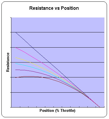
Unfortunately, the controller gets more non-linear the further it gets turned down. The following graph shows the linearity of the base controllers and several controllers made from a 25 Ohm base controller and various secondary resistors. The stock controller is shown as a straight line in the graph. The curved lines represent modified controllers. As can be seen from the graph, the controller becomes progressively more non-linear the further it's sensitivity is "turned down". As the bottom line on the graph shows, taken too far the resistance can actually go up at part throttle. To avoid this problem, a good rule is to limit the adjustability so that the controller cannot be turned down to less than 60% of its base value.

Figure 1
Figure 2a provides a schematic for a downwardly variable resistor controller. Note that two resistors are used in parallel with the Parma resistor. The variable resistor (R1) provides the sensitivity adjustment. The fixed resistor (R2) provides the floor or a lower limit for the controller. I usually chose R2 so that the controller cannot be turned down to less than 60% of its base value. This means that our sample 30 Ohm controller could be adjustable from about 22 Ohms to 15 Ohms. The upper limit of the controller has been lowered approximately 3 Ohms as the parallel resistors are in the circuit at all times. This can be changed, if desired, by adding a switch to cut out the parallel resistors if necessary.
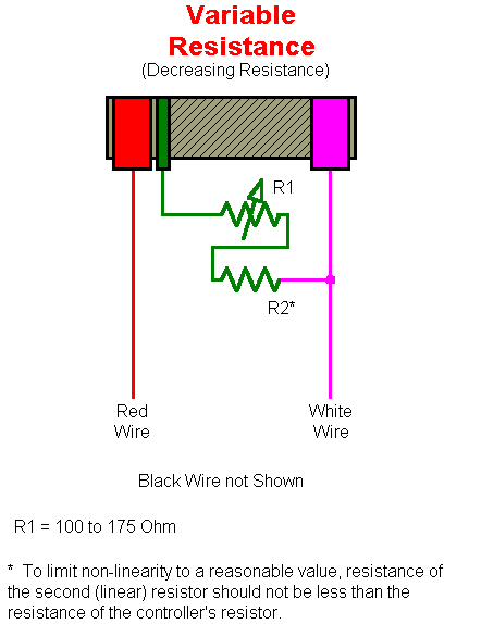
Figure 2a
(Dial-Down Controller)
Click on this link to download an Excel spreadsheet to calculate the minimum and maximum values for a parallel resistor controller you are thinking about building to verify the minimum, maximum values and the linearity of the resulting controller. The spreadsheet shows the high and low end of the controller made from the Parma resistor, R1 and R2. Depending on the position of the R1 "dial" the resultant controller will be operating on a line somewhere between the two extremes.
I recently used this trick to change the curve or "personality" of a Trek electronic controller. The stock controller was too quick on the bottom end. By adding a fixed resistor in parallel with the controllers variable resistor I was able to change the curve and soften up the bottom end. The resulting controller was easier to drive and gave faster and more consistent laptimes. I did the same trick on a second Trek controller and the controllers owner independently confirmed my findings.
The sensitivity can be decreased as well. Figure 2b illustrates a circuit that can make a 60 Ohm controller feel and act like a controller with a value from approximately 65 Ohms to over 100 Ohms. This circuit is recommended only if you cannot find a base resistor that is higher than what you want. The resistance of the base resistor is increased by using the same additional resistors to act as an additional load on the main resistor. This increases the voltage drop on the main resistor and makes it act like it has a higher resistance than it actually has. A good analogy for how the "rising rate" controller works is think about what happens when you get another car or a "rider" in your lane. When the second car drops in your lane your car slows down because the additional current required by the second car increases the voltage drop across the base resistor and decreases the voltage going to the cars.
An upwardly adjustable, or rising rate, controller is useful for T-jet racing as the highest value resistor Parma made when this article was first written was 60 Ohms. The following circuit allows the adjustment of the resistor from approximately 65 Ohms to approximately 120 Ohms. Exact numbers are unavailable as the value of the car/controller resistor combination is dependent on the current draw of the car being driven. The prototype "rising rate" adjustable controller was tested by several racers at the 2002 NITRO Prairie Thunder Fray race. These racers immediately wanted additional details and/or bought the spare (adjustable brake) potentiometers I had with me so that they could build their own. The prototype used two 100 Ohm / 10 Watt block resistors from Radio Shack wired in parallel as shown to form a 50 Ohm/20 Watt resistor. A 100 Ohm 25 Watt potentiometer was used as the variable resistor. Note that the brake wire has to be connected to the track for the circuit to work. Variable brakes and in-line resistance can be adapted to the "rising rate" controller as well. The variable brakes interact with the rising rate controller but some adjustability can be obtained without adding a micro switch to the controller to automatically turn off the rising rate feature when the trigger is released and brakes are applied.
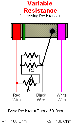
Figure 2b
(Rising-Rate Controller)
– The Parma controller offers dynamic braking. Dynamic braking works by disconnecting the power to the motor and putting a direct short across it. This turns the motor into a generator and gives the motor a load to drive power into. The load caused by the short provides the braking effect. In the larger scales this type of zero resistance (impedance) dynamic braking works fine. Unfortunately in HO scale zero impedance brakes effectively emulates the driver throwing out an anchor. The car slows so fast that its almost uncontrollable. The braking effect can be reduced by adding resistance to the brake wire. An adjustable resistor allows you to adjust the brakes from car to car and from lane to lane. I recommend a 100 or 150 Ohm adjustable resistor for the brake pot.Step Two Adjustable Brakes/Coast
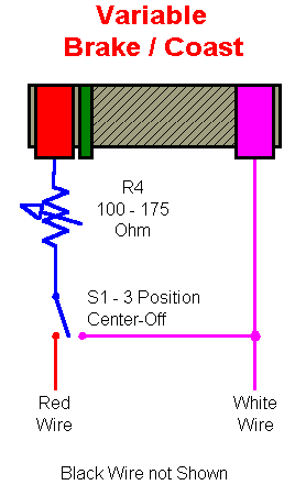
Figure 3
(Variable Brakes/Coast)
Step Three Inline Resistance
- Too much punch? Add inline resistance. This resistor is added to the white wire and is in the circuit at all times. This softens the car coming out of the corners as the current is higher than when the car is at full speed. A three ohm adjustable resistor is recommended for this application. The fact that the resistor is in the circuit at all times wont hurt the cars performance as the difference between stall and running currents on a permanent magnet DC motor can be 10 or more. For example at 16 Ohm T-jet motor with a very good electrical system will have a current draw of an amp when the motor is stalled (not turning). When running at full speed the current draw of the same motor is 0.1A or less. With a three ohm resistor and an 18V power supply the above T-jet motor will see 15V at stall and more than 17.7V at full speed.
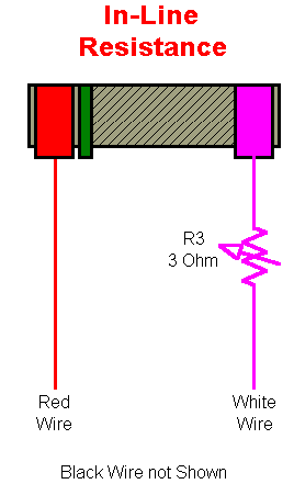
Figure 4
(In-Line)
Figures 2, 3 and 4 illustrate the individual segments of the adjustable controller. As you can see most of the modifications occur with the white wire (magenta in the above diagrams) and red wire. With the exception of the "rising rate" controller the black wire is untouched. A 5 Amp fuse and telltale light can be included in the White wire to prevent blowing the whole thing up if improperly hooked up or in case of a short in the track wiring or in the car. The telltale light is wired across the fuse terminals and will light up when the trigger is squeezed if the fuse is blown (or removed), power is on and there is a car on the lane. The fuse can be equipped with a bypass switch that will enable you to bypass a blown fuse if required. However, be very careful to check the wiring if you're going to bypass a blown fuse as with the fuse bypassed you now have no protection for the controller.
Ohmite Industries makes miniature 12-1/2 Watt potentiometers (pot for short) that are perfect for these applications. Use a three Ohm pot for in-line resistance and a 100 or 175 Ohm pot for sensitivity, brake and cost. 12-1/2 watts sounds low but these resistors were used exclusively in adjustable controllers since their inception in the early 80s with no problems. When you look at the duty cycle any resistor is only in the circuit for 20 or 30% of the time at rated current. The remainder of the time the resistors are either disconnected (open or short circuited) or operating at reduced current which limits the wattage requirement.
On my last "black box" resistor controller I used a three ohm in-line pot and a 175 Ohm dial-down pot. The coast/brake pot was made up from a 50 Ohm pot and a rotary switch with 25 and 50 Ohm block resistors to give me a coast/brake gross and fine control. This was done as things got a bit hairy running unlimited cars with just a 175 Ohm coast pot. The gross/fine controls gave me increased adjustability and a better feel. The black box was used with a family of four controllers whose base value ranged from 30 to 7 ohms.
Figures 2A and 2B show fixed resistors added in series with the dial-down pot. This limiting resistor prevents turning the controller down (or up) too far and is usually has the same resistance value as the controllers base resistor. 10 Watt block resistors from Radio Shack work well for this application. The potentiometers can be obtained from a local electronic parts distributor or on line from Newark Electronics. The resistors, switches, fuses and other gizmos can be mounted on the controller or in a separate "black box". If you're using a separate box then mount the limit resistor in the controller handle instead of the box as the limit resistor value will be different for different controllers. Use a good grade of rosin core solder, plan and take your time. A plug can be added on the line from the controller to the box containing all the gizmos to allow you to change base controllers.
Step Four?
There's more? Without going into too much detail, passive devices can be added to a Parma resistor controller that soften the car's response but don't take over control. A choke or inductor acts like an in-line resistor for a brief instant when the car accelerates but then removes itself from the circuit to allow for maximum top speed. Great for powering out of those tight corners. Without inline choke I never would have won the 85' Michigan State Superstock title and probably not have won the HOPRA Modified National and Restricted Open Championships in the summer of 87' followed by the HOPRA Winter-Nationals Title the following winter. The cars were good but teamed with that controller they were unbeatable. I have had that little trick in my box since the mid 80's and am finally admitting its existence. Is it still an advantage with today's transistor controllers? Am I still using it? What is the rating of the inductor? Sorry, the answers to those questions remains a secret. There's also a little trick that can be done with the brake but . . . I've already told too much for now. All of the tricks are out. Those who want to should be able to figure out what's in the "black box" that's connected to my DR controller shown on one of the other pages on the Siberia Racing site on on the new M-Magic controller. For the rest of you, Step 4 will be fleshed out a bit later.Steve "Maddman" Medanic
Back to the Tech Pages Menu Page
Revised 10/1/2006)